Hello guys, i want to change the internal wiring to improve the singlas quality ( rca->selector->potentiometer->premamp->ampl) . Do u have any suggested wires thay i can use ?

>>> Internal-wiring.
>>> 15 cm
ANY will do, even a piece of coat hanger.
NO possible sound influence.
Let´s avoid just ANOTHER cable thread, we got rid of a nasty one only 2 or 3 days ago.
If it´s already wired (I guess it is), leave as-is, you will NOT change signal quality.
>>> 15 cm
ANY will do, even a piece of coat hanger.
NO possible sound influence.
Let´s avoid just ANOTHER cable thread, we got rid of a nasty one only 2 or 3 days ago.
i want to change the internal wiring to improve the singlas quality
If it´s already wired (I guess it is), leave as-is, you will NOT change signal quality.
Some believe cables make a difference, some don't. The problem is each camp tries to change the mind of the opposition, which leads to heated debates, sometimes amusing, often boring. Me I believe in differences, but I don't care what other people think: Afterall, this is the Internet Free Country and I'm no missionary. 🙂
On to the amps: most commercial ones are built to a price and use the cheapest (= crappiest) possible components. If it's an amp worthy of attention, I'd change the input and the output, connectors and wires. My main speaker cables are the Kimber 4TC, and I use leftovers to rewire the output part of a worthy amp. There're some Chinese variants of the Kimber with a slightly different geometry and a much lower price tag.
If it's a vintage amp, like last century, I'd also check the capacitors and the resistors: polypropylene and metal film are the way to go. Also check the voltage rating of the 'lytics: often you find part rated at 450V for a nominal HV of about 400V, but at startup, the HV can reach 500+V before the tubes pull current.
It´s not "belief" but hard fact: 15 cm of wire inside a metallic chassis will change NOTHING, neither heard nor measured, it´s not "opinion" but testing
"Belief" belongs in Religion, not here.
In any case, the OP will not improve anything, and that´s the original question.
"Belief" belongs in Religion, not here.
In any case, the OP will not improve anything, and that´s the original question.
Wow! Quick to put on your war paint!
Rest assured, I'm not picking a fight, especially in this case where you may not be wrong.
The OP needs to post some pics to help determine the worthiness of the op.
Rest assured, I'm not picking a fight, especially in this case where you may not be wrong.
The OP needs to post some pics to help determine the worthiness of the op.
To put things black over white; let's suppose that changing the wire you add or remove say, 10pF over an impedance of 100Kohm. Let the existent capacity to be 50pF.
Thus:
F(original) = 1/(2 pi R Corig) = 1/(2 × pi x 100K x 50pF) = 31.83KHz.
Now, take lower case:
F(lower) = 1/(2 pi R Cadd) = 1/(2 × pi x 100K x 60pF) = 26.52KHz.
Once again with higher:
F(high) = 1/(2 pi R Clow) = 1/(2 × pi x 100K x 40pF) = 37.8KHz.
I believe only a bat can listen the difference.
Thus:
F(original) = 1/(2 pi R Corig) = 1/(2 × pi x 100K x 50pF) = 31.83KHz.
Now, take lower case:
F(lower) = 1/(2 pi R Cadd) = 1/(2 × pi x 100K x 60pF) = 26.52KHz.
Once again with higher:
F(high) = 1/(2 pi R Clow) = 1/(2 × pi x 100K x 40pF) = 37.8KHz.
I believe only a bat can listen the difference.
the only rule that I respect is to flatten the cables as much as possible and to separate the "tension" cables from the "signal" cables as much as possible, ideally on either side of the chassis, laid in the corners.
I don't care about the length of the wires though.
I don't care about the length of the wires though.
Can you post photos of the amp?
Attachments
To put things black over white; let's suppose that changing the wire you add or remove say, 10pF over an impedance of 100Kohm. Let the existent capacity to be 50pF.
Thus:
F(original) = 1/(2 pi R Corig) = 1/(2 × pi x 100K x 50pF) = 31.83KHz.
Now, take lower case:
F(lower) = 1/(2 pi R Cadd) = 1/(2 × pi x 100K x 60pF) = 26.52KHz.
Once again with higher:
F(high) = 1/(2 pi R Clow) = 1/(2 × pi x 100K x 40pF) = 37.8KHz.
I believe only a bat can listen the difference.
Its true but its not about the math. Its about the cable quality/thickness/insulation etc which is gonna changwe the sound dramatically. I have done the testing and it has a direct impact on the sound. Thats why I was asking to hear different opinions. Its like capacitors/resistors . The can have the same nominal values but at the end of the day a rhodium resistance will sound completely diffrent compared with a carbon or metal thin film one.
Last edited:
The only time even shielded cable is needed is when ground is disconnected at one end. Electrostatic shielding is needed when magnetic can’t be used. Whenever an equal ground return current actually occurs along with the signal, ie., rca to pot, feedback to input cathode, twisted pair will suffice - and has the lowest capacitance. Keep it spaced from, or at right angles to any conductor carrying an AC current (or DC with ripple since that is AC). Twisted pair works well for keeping AC heater power radiation down, and this works both ways. Premium 12AX7s even have the filaments themselves twisted to keep the hum down where it needs to nanovolts. The number of dB of coupling couldn’t care less which pair is the source and which is the load.
What you have to worry about more is the internal wiring between stages. Oscillation due to parasitics (even an extra 10 pF) can occur way the hell above audio - and you still have to get rid of it. Keep it as simple and direct as possible.
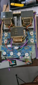
Now that I see that pic - I might be inclined to rethink the overall layout, maybe even find a bigger chassis. Sticking a power trafo right in the middle of everything is usually NOT a good idea. What you end up having to do just to get power to everything invites ground loops, and no amount of twisting or shielding gets rid of those. It is a classic mistake that even manufacturers of big SS amps do all the time, and causes newbies an awful lot of headaches.
What you have to worry about more is the internal wiring between stages. Oscillation due to parasitics (even an extra 10 pF) can occur way the hell above audio - and you still have to get rid of it. Keep it as simple and direct as possible.
Now that I see that pic - I might be inclined to rethink the overall layout, maybe even find a bigger chassis. Sticking a power trafo right in the middle of everything is usually NOT a good idea. What you end up having to do just to get power to everything invites ground loops, and no amount of twisting or shielding gets rid of those. It is a classic mistake that even manufacturers of big SS amps do all the time, and causes newbies an awful lot of headaches.
I can see two or three cooked resistors
hahaha yes os the yaqin one but the one what is left the same is the boards, i am changing them now and i decided as i opened it I decided to change again the cables . I put some profibus which did the job , and some friends told me put mogami but i just am asking for opinions for specific cabling the have been tested and it worth testing.
Thanks for doing the math. I doubt even bats could hear this kind of diff.... let's suppose that changing the wire you add or remove say, 10pF over an impedance of 100Kohm...
I believe only a bat can listen the difference.
However, the reasoning is flawed: at the input, the resistance in shunted by the output of the preamp, usually a few K max., which pushes the low pass effect an order of magnitude (or more) up.
But...
... or over compensate, which may lead to some ridiculous situations like with most Leak tube amps where the open loop BW is only a few KHz! Of course, they did this in order to brag about their "Point One" (% of THD)....
What you have to worry about more is the internal wiring between stages. Oscillation due to parasitics (even an extra 10 pF) can occur way the hell above audio - and you still have to get rid of it ...
Other things to watch out for: a resistor shows signs of overheating, the one in between the 2 filter caps; use a bigger one, and move it off the PCB. Another thing I do routinely is to replace the bias pots with 20 turn ones. Also, what appears to be the input selector at the bottom of the pic could use an upgrade, or, better still, a relay board mounted near the RCA's.
In addition to replacing bias pots with 20 turn - hang a high value (say 2.2M) resistor from the wiper to the negative side of the pot. 20 turn are less likely to get intermittent (and make you red plate) but it can still happen.
1) the OP only wants to change brand - colour - whatever of wire,
2) seeing that amp build, it has WAY larger problems than 15 cm of wire.
3) I already see finger thick shielded wire (over a 15 cm length path let´s remember), logic "improvement" would be upgrade to wrist thick?
It does not work that way, it´s not a multi kW transmitter antenna feed.
4) If anything, shielding/grounding/layout could be improved, if necessary; "sound quality" is undefinable and not part of the equation , specially here.
Not affected by "wire quality" which was asked about.
5) not me the one who will criticize a beginner, on the contrary I encourage actual builders (harder to do) than simulators (easier) and others who work on the virtual domain, but here I would suggest to put that build in about twice the currently shown space.
"you can´t put a gallon milk inside a quart jar"
So much iron almost edge to edge will most probably result in induced hum and Audio in general, even without amplification.
he never even asked about rerouting, layout, grounding, etc. , so ....Do u have any suggested wires thay i can use ?
2) seeing that amp build, it has WAY larger problems than 15 cm of wire.
3) I already see finger thick shielded wire (over a 15 cm length path let´s remember), logic "improvement" would be upgrade to wrist thick?
It does not work that way, it´s not a multi kW transmitter antenna feed.
4) If anything, shielding/grounding/layout could be improved, if necessary; "sound quality" is undefinable and not part of the equation , specially here.
Not affected by "wire quality" which was asked about.
5) not me the one who will criticize a beginner, on the contrary I encourage actual builders (harder to do) than simulators (easier) and others who work on the virtual domain, but here I would suggest to put that build in about twice the currently shown space.
"you can´t put a gallon milk inside a quart jar"
So much iron almost edge to edge will most probably result in induced hum and Audio in general, even without amplification.
- Home
- Amplifiers
- Tubes / Valves
- Internal Wiring for Tube Amps