Hi and best wishes for 2023 !
Whilst putting the finishing touches to fixing a Hypex NC122MP amp in an aluminium enclosure, I accidently shorted the Vaux positive auxiliary supply (pin J6.1): there was a hiss in the speakers and the amp went dead - that moment when you want to reverse time by 5 seconds and replay without the silly oversight 🙁
After 30 min off mains, and checking that the SMPS shrinkwraped mains fuse is not blown (tested for continuity), feeding mains again to the board brings the standby SMPS J6.3 pin to nominal 5V, and after asserting the J6.9 PS Enable pin, the Vaux negative auxiliary supply (pin J6.2) is nominal -20V, but the Vaux positive auxiliary supply (pin J6.1) is around 500mV instead of 20V, and the board does not drive speakers when fed audio signal. The J6.7 DC error pin isn't activated.
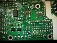
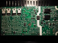
Visual inspection of the top part of the board does not show any signs of arcs or blown components, however removing the bottom heatsink plate shows at least one obvious blown L15 SMD component (pictures attached).
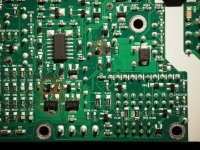
I don't have the schematics for the PCB, would anyone be able to put me on the right track to determine what that component value might be ? This L15 is one of those SMD's with no markings that I can see. Maybe there's a way to guess from a measurement of an equivalent component on the Vaux negative line (say L16 for instance), as there might by some symetry involved asks the newby naively ?
As can probably be guessed I am a just a hobbyist but at ease with DIY, equiped with a Voltcraft VC830 multimeter, a very fine tipped soldering iron, and the will to make good my f***k up however much effort I need to put into it 🙂 If need be, I can access hot air gun and more advanced measuring instruments.
Many thanks in advance for your help !
Cheers,
Pascal
Whilst putting the finishing touches to fixing a Hypex NC122MP amp in an aluminium enclosure, I accidently shorted the Vaux positive auxiliary supply (pin J6.1): there was a hiss in the speakers and the amp went dead - that moment when you want to reverse time by 5 seconds and replay without the silly oversight 🙁
After 30 min off mains, and checking that the SMPS shrinkwraped mains fuse is not blown (tested for continuity), feeding mains again to the board brings the standby SMPS J6.3 pin to nominal 5V, and after asserting the J6.9 PS Enable pin, the Vaux negative auxiliary supply (pin J6.2) is nominal -20V, but the Vaux positive auxiliary supply (pin J6.1) is around 500mV instead of 20V, and the board does not drive speakers when fed audio signal. The J6.7 DC error pin isn't activated.
Visual inspection of the top part of the board does not show any signs of arcs or blown components, however removing the bottom heatsink plate shows at least one obvious blown L15 SMD component (pictures attached).
I don't have the schematics for the PCB, would anyone be able to put me on the right track to determine what that component value might be ? This L15 is one of those SMD's with no markings that I can see. Maybe there's a way to guess from a measurement of an equivalent component on the Vaux negative line (say L16 for instance), as there might by some symetry involved asks the newby naively ?
As can probably be guessed I am a just a hobbyist but at ease with DIY, equiped with a Voltcraft VC830 multimeter, a very fine tipped soldering iron, and the will to make good my f***k up however much effort I need to put into it 🙂 If need be, I can access hot air gun and more advanced measuring instruments.
Many thanks in advance for your help !
Cheers,
Pascal
Attachments
not the best answer in the world, and I don't have a schematic either, but L16 looks a whole lot like L15. IT might be a good starting point if you are going to try to put a new inductor in there.
Sheldon
Sheldon
Looks like an inductor, or something like an RF bead.
L16 next to it looks similar. Maybe its a fuse.
If I were you, I would take the chance and just short it.
But don't blame me if ...
Jan
L16 next to it looks similar. Maybe its a fuse.
If I were you, I would take the chance and just short it.
But don't blame me if ...
Jan
Mant thanks for your advice ! The blown putative inductor fell off the PCB by itself, I've scanned both sides with a microscope and there are strictly no markings to guide a replacement. I guess I'm left with desoldering L16 & crossing fingers it is the L15 twin, getting a LCR meter to measure its inductance and try to guess which replacement to order (I'll be missing max current & such data). Can an entry LCR meter hope to measure such an SMD inductance? I'm hoping a slightly off inductance would yield degraded performance rather than anything more serious...
I must confess I was also toying with the idea of shorting the L15 pads now the SMD has dropped off, maybe this would allow me to test if this brings back the Vaux positive power, albeit in degraded mode, thus allowing a check that this component is the only one fried? Indeed in the attached picture I've located what looks like a trail of components that have visually not blown, but their soldering points have changed aspect (gone shiny) compared to their twins in what I imagine is the Vaux negative circuit. I'm concerned that if their outside soldering got that hot, the component internals might not be pretty sights even if ok from the outside 🙁
If it was a fuse, wouldn't it have a PCB code not starting with "L" ? Pardon my ignorance if it is maybe common practice to use an inductor as a fuse at such micro scale.
Attachments
Well, Vaux supplies 1A max per rail.
Check I've read the correct datasheet for your model.
Ask Hypex for the part details - worst they can do is refuse to tell.
Check I've read the correct datasheet for your model.
Ask Hypex for the part details - worst they can do is refuse to tell.
Indeed you are right, it's on the datasheet, 1A for this model.Well, Vaux supplies 1A max per rail.
Check I've read the correct datasheet for your model.
Ask Hypex for the part details - worst they can do is refuse to tell.
Yeap, I was wondering about asking Hypex, I don't know what is the norm for such info, but Hypex seem to have particularly good support for the DIY community, plus in this day and age of shortages of parts and environmental awareness it would make sense to support repairing. I'll write and report back.
I wrote last night to Hypex tech support via their online form, and they answered first thing this morning! Kudos for the Hypex support, they could have replied this is proprietary data, or that I should send the module to an approved repair center, but instead they provide free help to a noname DIY silly enough to have blown their product. They even go further than my request and hint to other components to check. Needless to say I am so darn impressed 🙂
I'm posting the reply here as it may help someone in the same situation:
I'll try and order those parts and progressively replace them on the PCB.
I'll report back, fingers crossed to the sound of music 🙂
I'm posting the reply here as it may help someone in the same situation:
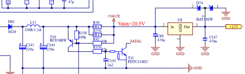
The Vaux schematic is attached.Please find the schematic of the Vaux circuit below.
The components in question are:
L15: 330R/1.5A bead
C147: 470nF
D74: BAT54SW
U8: 7812 SOT89
I suggest also checking resistors R39 and R270. These are there for overcurrent protection and can break due to high load or short circuit.
These resistors are 0,47 ohm, preferably 500mW.
I'll try and order those parts and progressively replace them on the PCB.
I'll report back, fingers crossed to the sound of music 🙂
Attachments
Last edited:

That's really great to hear. In addition to being cheap and amazing sounding, the people behind the product are good guys. I'm really impressed, and I'm glad I've got a bunch of Hypex stuff.
Good luck with the repairs.
Sheldon
Good luck with the repairs.
Sheldon
I ordered replacements for all 5 suspect components from mouser, and started progressive replacement, starting with the vaporized inductor L15.
Turns out just the first step of soldering a new L15 ferrite bead brought back exactly 20.5V to Vaux, and brought back sound amplification to life 🎶 !
Would you now just leave the amp as is, or go all the way and replace the other 4 components ? Said otherwise, could slightly degraded performance of these have any impact on amplifier sound quality, or if they are functional then that's all there is to it ?
Geez am I happy though 🙂
I'll follow the wise advice, better is sometimes the enemy of good...I'd quit while you are ahead.
- Home
- Amplifiers
- Class D
- Hypex NC122MP repair