I’ve read various blog entries about the LM3886 and the circuits people have made
Two suggestions I’ve seen that don’t always seem universal are the following, and I’m just curious how often they are implemented?
1) the data sheet sort of makes a passive mention about a 220pf capacitor between the inputs to help with oscillations, especially with those that come in via the input terminals. Is that pretty standard? I don’t see it in a lot of PCBs, so I’m guessing the ones who do it solder directly to the lm3866 pins?
2) I’ve also seen mention of putting a larger 100k resistor between the input and ground, but before the DC blocking capacitor. Apparently this helps prevent the capacitor from accumulating a charge when no input is connected. What’s the side effect of doing vs not doing this?
Thanks.
A small C cut the high frequency response reducing the risk of selfoscillation and RF from external fiels pick up.
The R tends to maintain the input coupling cap DC and prevent possible external DC from previous stages in case the last has output cap wirhout resistance to ground, closing the DC circuit.
The R tends to maintain the input coupling cap DC and prevent possible external DC from previous stages in case the last has output cap wirhout resistance to ground, closing the DC circuit.
Without the 220 pF cap across the inputs the LM3886 will show some spurious oscillation as the amp exits clipping on the positive swing (see below). The 220 pF cap fixes that but creates overshoot in the transient response. That's cleaned up with the 47 pF + 20 kΩ across the feedback resistor.
Many LM3886 PCBs just implement the Typical Application Circuit which doesn't show the additional components. But if you bother to measure the implemented circuit, you'll notice the oscillations.
Tom
Many LM3886 PCBs just implement the Typical Application Circuit which doesn't show the additional components. But if you bother to measure the implemented circuit, you'll notice the oscillations.
Tom
Attachments
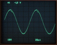
They are just at clipping though? I’ve never approached that yet. I think on your website you use a 470pf to ground instead - does that essentially serve the same purpose?Without the 220 pF cap across the inputs the LM3886 will show some spurious oscillation as the amp exits clipping on the positive swing (see below). The 220 pF cap fixes that but creates overshoot in the transient response. That's cleaned up with the 47 pF + 20 kΩ across the feedback resistor.
Many LM3886 PCBs just implement the Typical Application Circuit which doesn't show the additional components. But if you bother to measure the implemented circuit, you'll notice the oscillations.
Tom
Could you point me to that 470 pF cap? If it goes to ground it sounds more like an EMI/RFI filter. Certainly not a compensation cap.They are just at clipping though? I’ve never approached that yet. I think on your website you use a 470pf to ground instead - does that essentially serve the same purpose?
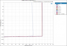
The spurious oscillations start once the output voltage approaches the rail voltage, so within the last volt or so of clipping. That limits the max output power of the LM3886. Basically you don't get the performance you pay for unless you add Cc across the inputs and Cf + Rf2 in the feedback path. The difference isn't enormous (see attached), but some may legitimately be concerned about the oscillations as RF is known to kill tweeters. Also the parts only add a few cents to the build so why not just add them and have a more robust amp?
Tom
Attachments
Sorry, it's the 680pf CC you have on your LM3886 amplifier design article.Could you point me to that 470 pF cap? If it goes to ground it sounds more like an EMI/RFI filter. Certainly not a compensation cap.
The spurious oscillations start once the output voltage approaches the rail voltage, so within the last volt or so of clipping. That limits the max output power of the LM3886. Basically you don't get the performance you pay for unless you add Cc across the inputs and Cf + Rf2 in the feedback path. The difference isn't enormous (see attached), but some may legitimately be concerned about the oscillations as RF is known to kill tweeters. Also the parts only add a few cents to the build so why not just add them and have a more robust amp?
Tom
Attachments
One other small issue I've been trying to track down is a quiet, high pitched sound I hear occasionally. The amplifier I built has a pretty tight PCB layout with all the decoupling capacitors you recommend on your site. I have the optional components and both the Theile and Zobel networks. It sounds pretty incredible, and it's given new life to old music.
But when I'm sitting on the couch with nothing playing, every once and a while I'll hear a small high pitched sound coming from the speakers. It's almost like an insect is flying near my ear. It only lasts about 5 seconds, and then it stops. I thought maybe it's oscillating, but I haven't been able to see anything on the scope yet, and I only hear it once every ten minutes or so. It may just be something nearby that's radiating at that interval, and it's just being picked up by the inputs. But just wanted to ask your thoughts while you were here if you've ever seen it oscillate and no volume (but with an input connected)? The gain is 26dB, so it should be stable I'd think.
But when I'm sitting on the couch with nothing playing, every once and a while I'll hear a small high pitched sound coming from the speakers. It's almost like an insect is flying near my ear. It only lasts about 5 seconds, and then it stops. I thought maybe it's oscillating, but I haven't been able to see anything on the scope yet, and I only hear it once every ten minutes or so. It may just be something nearby that's radiating at that interval, and it's just being picked up by the inputs. But just wanted to ask your thoughts while you were here if you've ever seen it oscillate and no volume (but with an input connected)? The gain is 26dB, so it should be stable I'd think.
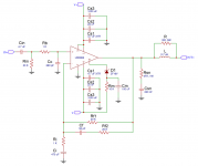
I think you have me confused with someone else. Cc = 680 pF in the figure above is part of an RFI/EMI filter. It's not a compensation cap.Sorry, it's the 680pf CC you have on your LM3886 amplifier design article.
This is what I write about the LM3886: Taming the LM3886 Chip Amplifier.
Odd with the squeal. That shouldn't happen. Is the amp in a grounded metal enclosure?
Tom
I think you have me confused with someone else. Cc = 680 pF in the figure above is part of an RFI/EMI filter. It's not a compensation cap.
This is what I write about the LM3886: Taming the LM3886 Chip Amplifier.
Odd with the squeal. That shouldn't happen. Is the amp in a grounded metal enclosure?
Tom
Ah ok, sorry. I thought this was from your site as well - https://www.circuitbasics.com/design-hi-fi-audio-amplifier-lm3886/ But I saw just now it's not!
So you think a 220pF cap is a good thing to add across the pins then?
I think you have me confused with someone else. Cc = 680 pF in the figure above is part of an RFI/EMI filter. It's not a compensation cap.
This is what I write about the LM3886: Taming the LM3886 Chip Amplifier.
Odd with the squeal. That shouldn't happen. Is the amp in a grounded metal enclosure?
Tom
And yes, I've tried it both ways - connecting the earth directly to the star ground, and also through a ground lift. That squeal still shows up in both configurations. Although most of the time the cover is off as I'm tweaking stuff.
Please see Posts #3 and #5 above.So you think a 220pF cap is a good thing to add across the pins then?
You can see my recommendations for grounding here: Taming the LM3886 - Grounding.And yes, I've tried it both ways - connecting the earth directly to the star ground, and also through a ground lift.
I've never had RF interference show up as squealing, but I suppose it's possible for it to manifest that way. Usually, it shows as clicking or buzzing, so I'm leaning more in the direction of instability here.That squeal still shows up in both configurations. Although most of the time the cover is off as I'm tweaking stuff.
Especially GSM cell phones are good for generating that brrr-brr-brrrtt when a call or SMS comes in. That's because GSM uses a 200 Hz burst where the RF is turned on/off at that rate, so you get a ~200 Hz square wave on the output of audio circuits if they're susceptible to EMI/RFI.
If the squealing goes away when you put the cover on, it's most likely due to EMI/RFI.
Tom
You can see my recommendations for grounding here: Taming the LM3886 - Grounding.
I've read that post.. In all honesty, I find it a bit confusing. Maybe because you simplify some stuff for the simulation. LIke, where does the input ground go? I think you briefly mention tying it into signal ground. But it's not really talked about past that, or even shown on your diagrams. You also talk about using ground planes, but your diagrams show point to point. Don't get me wrong, I think you're a LM3886 genius, but I've read that post multiple times and I find I'm confused about what practically I'm supposed to do after reading it. Put yourself in my shoes - imagine you are a designing a PCB, and go read that post. What would you do? For me I'm not entirely sure, even after reading it. Maybe it's me, but I think you could probably expand on a few areas, namely what happens to the input ground (especially when it comes from something like a RCA connector), and how ground planes would fit in. I absolutely appreciate the work you put into the simulations and the article, but I think it's missing a "how do you interpret this?" section. The "layout is the circuit" sounds great, but it didn't resonate with me. I think I need to be shown a diagram, especially one with ground planes. Just my 0.02! Like I said, I think you've done amazing work, I just think that blog entry could be a bit better for people like me who are coming in a bit cold.
Last edited:
The input return ground wire must return as close as possible to Ci as you called it in the diagram, because this is the point where input and outputs joins toguether and close its paths. The IC "sees" the difference between inverting and non inv. inputs.
Or maybe you're making it more complicated than necessary by thinking in terms of a star ground rather than focusing on what the grounding scheme is trying to accomplish.I've read that post.. In all honesty, I find it a bit confusing. Maybe because you simplify some stuff for the simulation. LIke, where does the input ground go? I think you briefly mention tying it into signal ground.
The central point of grounding (or any power distribution, really) is to keep the signal ground quiet so 'dirty' ground currents (and/or high currents) don't pollute the output of the amp. So let's start by identifying the 'dirty' currents:
- Currents through bypass capacitors
- Power supply currents
- Speaker return current
- Zobel network return current
- Ground current of the feedback network
So let's look at what's left:
- Input RCA ground
- Input EMI/RFI filter ground current
- Any other sensitive ground node
Join the 'dirty' power ground plane and the 'clean' signal ground plane/pour together at the speaker output ground terminal.
I do agree that the learning curve can be a bit steep, and way too many books on the topic start by drowning you in Maxwell's equations, which is not particularly helpful. Mark Montrose's book, Printed Circuit Board Design Techniques for EMC Compliance (ISBN: 978-0780353763) is one of the better books on the topic. As the title indicates he comes at the topic from an EMC/EMI angle, but the overall idea is the same for audio.
Tom

It's possible of course. but I don't think so. Read your concluding paragraph - it doesn't tell the reader what to do. It should exclaim, with joy, "connect input GND to signal gnd to power gnd, and that is the best you can accomplish". But it doesn't say anything of the sort. Even in the previous paragraph, you talk about gnd_sig with no mention of the input ground. Like I said, I think your analysis is amazing, just incomplete IMO, at least from an implementation perspective.Or maybe you're making it more complicated than necessary by thinking in terms of a star ground rather than focusing on what the grounding scheme is trying to accomplish.
Maybe I need to add a video where I explain it using a joyous interpretive dance... 🙂
This is the first paragraph from the An Improved Grounding Scheme section (emphasis added):
Tom
This is the first paragraph from the An Improved Grounding Scheme section (emphasis added):
From a feedback theory point-of-view, it seems apparent that if the voltage across the load is what we intend to control, the feedback voltage should be measured as close to the load as possible. This means that GND_SIG should connect to GND_LOAD. The resulting circuit is shown below along with the simulation result.
Tom
But where is in the input GND? That's important, no? You gloss over it, but it seems it's a huge source of ground noise for a lot of people. You passively mention tieing it into SIG_GND, but then never talk about it again.. But I think it's a bigger deal.Maybe I need to add a video where I explain it using a joyous interpretive dance... 🙂
This is the first paragraph from the An Improved Grounding Scheme section (emphasis added):
Tom
And yes, I'm all for an interpretive dance! My point is I think your article is great, but you wrote it as an engineer who already knew what he was talking about. I think you need to revisit the article from the perspective of people not entirely sure, and fill in some blanks.But where is in the input GND? That's important, no? You gloss over it, but it seems it's a huge source of ground noise for a lot of people. You passively mention tieing it into SIG_GND, but then never talk about it again.. But I think it's a bigger deal.
I don't. I only operate with two grounds: A dirty one and a clean/quiet one.But where is in the input GND? That's important, no? You gloss over it, but it seems it's a huge source of ground noise for a lot of people. You passively mention tieing it into SIG_GND, but then never talk about it again.. But I think it's a bigger deal.
To me it's pretty obvious that you want the input to be on the clean ground. Can you come up with an argument for why the input should be referenced to the dirty ground? Keep in mind that anything that causes the input to wiggle will be amplified by the amp.
The Taming series is not intended to be a cookbook. I intended it as more of a technical reference. I'll keep your comments in mind if/when I revisit the article series, though.
Tom
- Home
- Amplifiers
- Chip Amps
- Extra LM3866 components