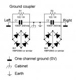
I came across this picture while searching grounding articles. Supposedly the anti parallel diodes and x2 capacitor protect from EMI while still providing ground protection.
Any thoughts on incorporating this on a tube amp?
Any thoughts on incorporating this on a tube amp?
Generally a good plan.Any thoughts on incorporating this on a tube amp
The bridge rectifier is probably better;
all components should be dimensioned to support a continuous fault current greater than that which is certain to blow the fuse protection of the supply it is connected to.

I guess I'm lucky - I just ground the chassis.
I did have to float the CD player though - it was the only ground related hum in the system.
I did have to float the CD player though - it was the only ground related hum in the system.
I found the original post here:
https://www.diyaudio.com/community/threads/hum-in-tube-amp.226191/page-9#post-3412354
It does indeed eliminate ground currents (and thus the voltage drop across the interconnect shield conductor that causes it to contaminate the signal) between equipment with slightly different "ground voltages." I think I've seen it before, but not sure if I like it. I do agree with others that the circuit should carry enough current to blow the mains fuse or circuit breaker in a fault, which is a LOT. Depending where the fault is, the interconnect cables could heat up and catch on fire if the breaker doesn't blow fast enough. If possible I would prefer the solution in the second schematic in that post.
At first I thought it had something to do with this circuit to remove DC from mains going into a power transformer (to me the circuit looked to be 'on the wrong side of the power transformer'), but no, this is meant to solve a different problem:
https://sound-au.com/articles/xfmr-dc.htm
https://sound-au.com/earthing.htm#s9
Of course there would be disagreement on whether to include up front or only use when needed. If you were dealing with high impedance sources like MI you would probably want to add up front.
Of course there would be disagreement on whether to include up front or only use when needed. If you were dealing with high impedance sources like MI you would probably want to add up front.
The diode bridge in the Broskie's ground lift implementation could be better utilized by shorting it diagonally to form a double anti parallel pair to boost its fault current capacity by 2, instead of having to have the fault current go through two diodes in series. By doing that the clamping voltage would be down by half, to one P/N junction drop around the PE, but that's probably more of desirable than a problem.

That Broskie thing looks unsafe to me, the bridge rectifier looks too small to guarantee enough current to trip the breaker.
In the worst-case failure of the mains "hot" (WRT Earth ground) short to chassis, any location of the short after the internal fuse can depend on the fuse to open. But if the short should occur before the fuse, for example where the mains enters the chassis, or in wiring between the mains entrance and the fuse holder, then protection will depend on the panel breaker to open, quite a different matter.
This is the case in America, but more civilized places have fuses in the mains cord itself, a safer location.
All good fortune,
Chris
This is the case in America, but more civilized places have fuses in the mains cord itself, a safer location.
All good fortune,
Chris
I've tried this scheme numerous times when I had a noise issue, it's never worked in my case. Re routing grounds or better layout had more effect.
Andy.
Andy.
Separating signal ground from safety ground (PE, or Protective Earth) is an issue completely separate from any amplifier internal "grounding" issue. Home audio systems suffer from their "single-ended" interconnections, where signal returns (also called "grounds") must, for safety's sake, be kept very near to chassis voltage, and chassis voltage must be kept very near Earth - otherwise a person could get hurt by touching two unconnected chassis, or one chassis or interconnecting wire and Earth (water pipe, etc.).
In the bad old days, we all just hoped for the best, but today things must be double insulated or have exposed conductors connected to PE. The second option has a drawback in that signal returns ("grounds") are duplicated by the safety grounds (PE), and are at least competitive in lowness of impedance. Current proportionally takes paths of least impedance, so signal current divides among the various available paths. If these extra paths are kept fairly local, everything with a PE connection all plugged into the same outlet strip and no external Galvanic connections (cable TV or whatnot), then home audio systems rarely have actual "problems" from PE ground loops.
But all single-ended interconnections (for the usual stereo components) are flawed by shared paths for signal return currents. Even in the case of PE-free components with single-ended stereo interconnections, each channel's return currents are shared 50/50 with the other channel. Both coax and twisted-pair wiring get their noise immunity by having equal magnitude and opposite polarity signal current in close proximity. This structural flaw is fundamentally caca doodoo, and we need to evolve past it.
All good fortune,
Chris
A working solution to the shared signal return issue is the Ground Breaking Resistor. It separates the signal ground and the input stage ground (where the input cable ground is connected).
I prefer a 2-conductor shielded interconnection cable: the internal conductors are hot and signal return (going to input stage GND), but the outer shield goes directly to the common signal GND. There is a 10R resistor between the input stage GND and the common signal GND, it breaks the return current of the other channel and effectively breaks GND loop hum.
I prefer a 2-conductor shielded interconnection cable: the internal conductors are hot and signal return (going to input stage GND), but the outer shield goes directly to the common signal GND. There is a 10R resistor between the input stage GND and the common signal GND, it breaks the return current of the other channel and effectively breaks GND loop hum.
- Home
- Amplifiers
- Tubes / Valves
- Anti parallel diode at ground