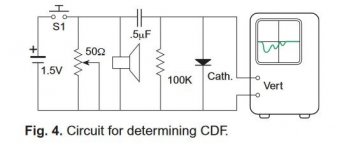
Various methods can be used to check the Damping Factor of a bare amplifier,
Here is a simple variation of that, this one looks at the amp with the loudspeaker it will be used with.
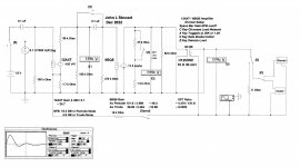
It needs a scope that can be triggered for a single shot. And a 1.5V Cell.
The test simulation is setup here in Electronic Workbench. The circuit is common.
Several switches labelled as keys on the keyboard allow a number of variations in the amp.
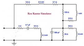
A standard R load or a choice of two loudspeaker simulators can be selected.
The first pass is on a speaker simulator by Ken Kantor. The amp is connected as an SE pentode.
The scope is set to trigger once when it sees a preset voltage change.
Over the next while I'll add to this. 🙂
Here is a simple variation of that, this one looks at the amp with the loudspeaker it will be used with.
It needs a scope that can be triggered for a single shot. And a 1.5V Cell.
The test simulation is setup here in Electronic Workbench. The circuit is common.
Several switches labelled as keys on the keyboard allow a number of variations in the amp.
A standard R load or a choice of two loudspeaker simulators can be selected.
The first pass is on a speaker simulator by Ken Kantor. The amp is connected as an SE pentode.
The scope is set to trigger once when it sees a preset voltage change.
Over the next while I'll add to this. 🙂
Attachments

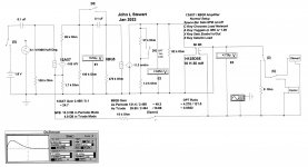
In Sim B2 the space bar closes the NFB loop, so ~13,3 DB (14 db is 5x).
The response to the step on the front end no longer shews a snakes tail. Damping looks good.
In Sim C2 the space bar opens the NFB, Key"A" creates a triode in the 6BQ5.
The damping again looks very good. But there is less audio power available.
Triode gain is ~14 db less than pentode (~10 / 50)
The response to the step on the front end no longer shews a snakes tail. Damping looks good.
In Sim C2 the space bar opens the NFB, Key"A" creates a triode in the 6BQ5.
The damping again looks very good. But there is less audio power available.
Triode gain is ~14 db less than pentode (~10 / 50)
Attachments


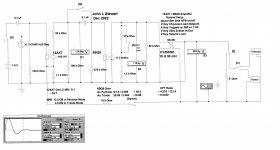
In test D2 I've used a loudspeaker simulator circuit I cobbled together about 20 yrs ago.
A very useful setup for both steady state & impulse testing. With a straight pentode drive the response goes thru the roof.
With the NFB reconnected in test E2 the response is completely damped.
These tests might lead one to look for another alternative to pentodes in a none FB amplifier. 👎
Or Not.😀
There is quite a bit on the web reference the Kantor simulator.
And an article reproduced from Stereophile magazine, that I won't attach here.
Don't need a long harangue about copyright law to get in the way.👎
Attachments

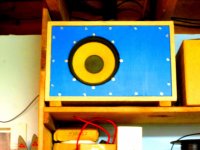
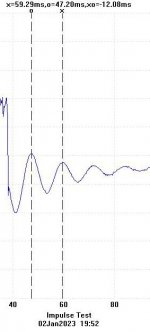
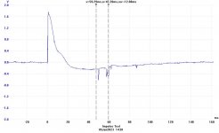
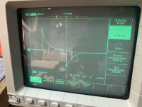
This test is in hardware, an 8 inch speaker in a closed box.
External dimensions are 8h x 11.5w x 9 deep, all in inches., The plywood is 5/8 thick.
The front face is set in 1/4 inch, Stuffing the numbers into the HP67 & turning the crank it looks like ~0.3 cu ft.
Built about 20 yrs using scrap materials, it runs all day in the workshop driven by a 6AQ5/6AU6 based amp.
So by direct driving the speaker with a 1.5V cell we get this response with a period of 12,08 mS. About 83 Hz.
Not well damped.
Something anyone can do at home provided a modern digital scope is available. 👍
Attachments
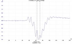
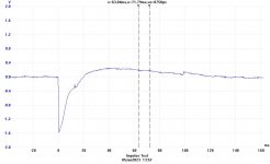
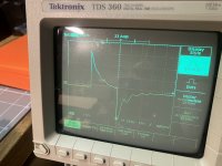
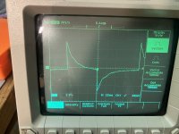
These tests use an amplifier driven by a step function at its input to drive the blue speaker of the previous test.
The amplifier is the PP Class AB2 I built as an experimental chassis.
The amp has standby switch so that HV can be removed from the circuit while the heaters are left on.
The first screen shot occurs at switch on of the HV, The amplifier is not yet stabilized in order to apply speaker damping.
The speaker rings as though on an open circuit.
The 2nd screen shot shews that the damping is working when a positive pulse is applied to the amp input.
And the 3rd screen shot shews the response when a negative pulse is applied to the input. No more speaker ringing.
Attachments
Lovely! Any chance of repeating that test, progressively adding series resistance until the resonance is critically damped (a la Tomcik)?So by direct driving the speaker with a 1.5V cell we get this response with a period of 12,08 mS. About 83 Hz.
Not well damped.
bondini,
You said: "adding series resistance until the resonance is critically damped".
I think if you put a resistance 'across' the loudspeaker driver leads, then when the 1.5V is removed the loudspeaker driver will be better damped.
You said: "adding series resistance until the resonance is critically damped".
I think if you put a resistance 'across' the loudspeaker driver leads, then when the 1.5V is removed the loudspeaker driver will be better damped.
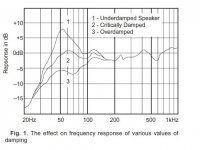
After two months .... finally a moment or two to re-visit Daniel Tomcik's 1951 observations on loudspeaker damping. Here is an old Philips 10" fullrange driver (AD 1065/M8) stimulated with a source impedance of 23 Ohm. The ringing response shows that it is under-damped.
Attachments
Driving a loudspeaker from a sufficiently high output impedance so that it is underdamped runs the risk of distortion at frequencies near resonance (47Hz for the driver tested). At the other extreme, over-damping by driving from a low output impedance restricts the low frequency response. As Tomcik puts it, "there is one value of damping at which the cone returns to rest in the quickest possible time without going past the rest position. This condition is called the critically damped state". To illustrate the effects on frequency response, have attached Bill Perkins' replica of Tomcik's original chart.
In the case of the bare Philips driver, testing shows that critical damping is achieved when driven with about 3 Ohms - I would expect that figure to change somewhat with the driver mounted in an enclosure.
In the case of the bare Philips driver, testing shows that critical damping is achieved when driven with about 3 Ohms - I would expect that figure to change somewhat with the driver mounted in an enclosure.
Attachments
Seen in this light, the images in post #5 indicate an over-damped response. Lest readers think that I am condemning or disparaging JH Stewart's experimental results (I am not!!) let me say that the interface between the power amp and the speaker presents designers of BOTH components with some tricky problems - the load impedance that best suits the amp is not necessarily that presented by the loudspeaker, and vice versa!
Current commercial manufacturers of amplifiers and loudspeakers may not have much room to move here. Low distortion amplifiers are more desirable and marketed as such and, as a consequence of (the entirely proper) use of negative feedback to achieve low distortion, they frequently have low output impedance (well under 1 Ohm) and a high "damping factor". Knowing this, commercial loudspeaker manufacturers tend to design with low output impedance in mind, with the consequence that some of our DIY tube/valve creations with relatively high output impedance may not be so good at driving loudspeakers of modern production!!
On the other hand, as DIY builders we have the opportunity to optimise amplifier distortion and output impedance, as well as loudspeaker damping - tricky as that might be 🙂
Several commercially available amplifiers of the 50s & 60s came with a variable damping control.
Used a combination of neg voltage & pos current FB from the loudspeaker. The user could adjust for
critical damping. Electrovoice comes to mind,
I tried it on a small PP 6AQ5 amp circa 1958. For the current sample I used a short length
of resistance wire. All a very worthwhile experiment, easy to do for the amateur.
👍
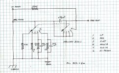
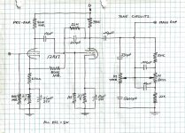
Found this in old notes.
This amp uses a Hammond 1618 meant as an OPT for Public Address systems. At the time I didn’t know much at all about NFB & amp stability so I used NFB sparingly, looks like only 4.5 db on this one.
The date on this is Aug 1956, I was working at Ferranti R&D. They were building a computer for the Post Office based on Philco SB100 Surface Barrier transistors. My first job there was testing 100s of these transistors for Ico, collector base leakage & putting them in different piles for later use. The scopes were TEK 514Ds, the D meaning there was a delay line in the vertical amp so the front edge of a step function could be seen.
The Positive Current FB is derived from a short piece of resistance wire on the speaker return lead. Earlier I’d found that moving the tap position along the resistance wire the damping of the speaker changed a lot. So much so that as PFB was increased the loudspeaker LF peak was first flattened & then inverted. Too much & instability was the result, oscillation.
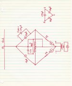
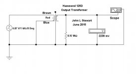
There was some HF ringing at the front edge of square waves, that was mostly fixed by a ‘gimmick’, a short piece of insulated wire tied to one of the OPT primary leads. In some unrelated tests later I found there is something like 200 pF more capacity to the OPT core from one of the primary leads than the other. I’ve included some tests I used to sort out that problem here. The capacity unbalance does create more problems when stabilizing a FB amplifier. I’m sure the Hammond OPTs of today are much better than in the 50s.
This amp uses a Hammond 1618 meant as an OPT for Public Address systems. At the time I didn’t know much at all about NFB & amp stability so I used NFB sparingly, looks like only 4.5 db on this one.
The date on this is Aug 1956, I was working at Ferranti R&D. They were building a computer for the Post Office based on Philco SB100 Surface Barrier transistors. My first job there was testing 100s of these transistors for Ico, collector base leakage & putting them in different piles for later use. The scopes were TEK 514Ds, the D meaning there was a delay line in the vertical amp so the front edge of a step function could be seen.
The Positive Current FB is derived from a short piece of resistance wire on the speaker return lead. Earlier I’d found that moving the tap position along the resistance wire the damping of the speaker changed a lot. So much so that as PFB was increased the loudspeaker LF peak was first flattened & then inverted. Too much & instability was the result, oscillation.
There was some HF ringing at the front edge of square waves, that was mostly fixed by a ‘gimmick’, a short piece of insulated wire tied to one of the OPT primary leads. In some unrelated tests later I found there is something like 200 pF more capacity to the OPT core from one of the primary leads than the other. I’ve included some tests I used to sort out that problem here. The capacity unbalance does create more problems when stabilizing a FB amplifier. I’m sure the Hammond OPTs of today are much better than in the 50s.
Attachments
-
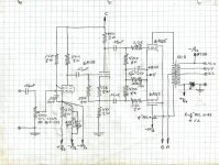 6AQ5 PP Amplifier with Positive Curent feedback Output Stage.jpg574.4 KB · Views: 76
 -
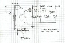 6AQ5 PP Amplifier with Positive Curent Feedback Power Supply.jpg417.2 KB · Views: 72
 -
 6AQ5 PP Amplifier with Positive Curent Feedback Input Selector.jpg462.7 KB · Views: 70
 -
 6AQ5 PP Amplifier with Positive Curent Feedback Preamp & Tone Controls.jpg578.8 KB · Views: 69
 -
 Push Pull Output Transformer High Frequency Imbalance.jpg289.7 KB · Views: 64
 -
 Hammond 125D OPT Check Capacity to Core from Brown Lead.JPG21.2 KB · Views: 59
 -
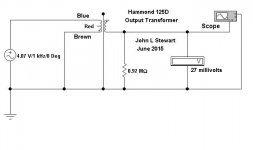 Hammond 125D OPT Check Capacity to Core from Blue Lead.JPG21.2 KB · Views: 65
Given what input? A step function?As Tomcik puts it, "there is one value of damping at which the cone returns to rest in the quickest possible time without going past the rest position. This condition is called the critically damped state".
I've become interested in what happens to the ringing at different frequencies, given say a tone burst as input. I'd love to find a software that can do that. Once upon a time you could do a LEAP design then back-export to LMS and derive a step. I don't recall that you could model tone burst response at different frequencies. Just making a box to Qtc=0.577 or whatever I don't think sheds insight into what a given driver will do in various boxes. My feeling is the overshoot varies at least somewhat in accordance with how far away the burst frequency is from the system resonance, though another part of my brain is feeling that does not hold up mathematically.
Someone somewhere posted some simulation showing that very low Qs actually were too slow to rise and slightly "too high" Qs like 0.8 or 0.9 looked more like the input. OK fine but I'd like to see that with say 10, 20, 40, 80, 120 Hz tone bursts as you make the box for a particular driver smaller and smaller.
That is a tall order asking someone else to do your work for you.
Why not put something together on the bench & try these ideas yourself?
Shew us what you can do. 🙂
Why not put something together on the bench & try these ideas yourself?
Shew us what you can do. 🙂
I'm not sure if you're replying to me. If so, I did not mean in real life. I meant in simulation, to judge tradeoffs in box design. I'm not aware of a software package that can do that although I badly hope there is one. The person who did post simulation I think was from a custom written Excel sheet - I might have downloaded that but having changed machines can't easily find it. It's somewhere although I also recall it needed rewriting to do what I wanted which I did not have enough expertise.That is a tall order asking someone else to do your work for you.
Why not put something together on the bench & try these ideas yourself?
You might have better luck posting in the diyAudio loudspeaker speaker forums rather than this tube amp forum, as the focus of the posts in this thread is the interaction of the amp and speaker, in particular the effect of damping due to low output impedance.I've become interested in what happens to the ringing at different frequencies, given say a tone burst as input ... I'd like to see that with say 10, 20, 40, 80, 120 Hz tone bursts as you make the box for a particular driver smaller and smaller.
Examining the effects of tone bursts is a fun idea - I recall but cannot now find an article exploring the amplifier side. I don't recall any write-up of the effects of tone bursts on loudspeakers, though they probably exist! Happy hunting!!
I did some amp, PP Class AB2 6V6s burst testing in a thread dated about Dec 2021. Some results are at #79 in thread Lowest Safe Loadline.Examining the effects of tone bursts is a fun idea - I recall but cannot now find an article exploring the amplifier side. I don't recall any write-up of the effects of tone bursts on loudspeakers, though they probably exist! Happy hunting!!
Attachments

- Home
- Amplifiers
- Tubes / Valves
- Loudspeaker/Amplifier Damping Study using Impulse at the Amp Input