Hello all,
Could I prevail upon your collective brains again.... I'm looking at my buddies 300b amp - its an early 90s british model from Arion who seem to be long gone. Anyway, he's had a channel imbalance problem for a long time, and asked me to take a look.
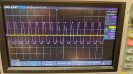
So the build quality isn't great, I found one or two cold solder joints, and a few resistors were certainly looking a bit tired, as they do when roasted. Nothing way off target though when comparing channel to channel. On the channel with lower output, I see distortion/reduced power creeping in quite early, and you can see this in the scope shot attached. Swapping valves between channels makes no difference.
I checked all resistors and replaced cathode coupling caps on the 6sn7 and 300b. I also replaced the 14K plate resistors on the 6sn7. The grid leak resistor on the 300b were very old looking carbon, and I replaced them as well. The volume pot shows a little channel imbalance, say if one track is 17.2k, the other will measure 16.9k but I don't see how that would reduce power output/balance given the distortion. The other oddity was the heaters for the 6sn7. It runs a 6VAC secondary, to a CRC of 4700uf-0r22-4700uf which only yielded 5.2V at the 6sn7 heaters which is very low) The first 4700uf was completely shot, but the second measured fine. I replaced that, and I now have 5.7V (dc) at the heaters but this seems too low to me still. I have 5.1V at the heaters of the 300b (this is a CRC supply).
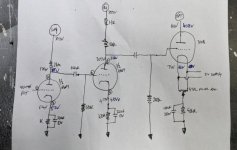
I drew out the schematic (attached below) with voltages marked in black and blue.
Anyone of you gurus see anything you would recommend me to look at?
Could I prevail upon your collective brains again.... I'm looking at my buddies 300b amp - its an early 90s british model from Arion who seem to be long gone. Anyway, he's had a channel imbalance problem for a long time, and asked me to take a look.
So the build quality isn't great, I found one or two cold solder joints, and a few resistors were certainly looking a bit tired, as they do when roasted. Nothing way off target though when comparing channel to channel. On the channel with lower output, I see distortion/reduced power creeping in quite early, and you can see this in the scope shot attached. Swapping valves between channels makes no difference.
I checked all resistors and replaced cathode coupling caps on the 6sn7 and 300b. I also replaced the 14K plate resistors on the 6sn7. The grid leak resistor on the 300b were very old looking carbon, and I replaced them as well. The volume pot shows a little channel imbalance, say if one track is 17.2k, the other will measure 16.9k but I don't see how that would reduce power output/balance given the distortion. The other oddity was the heaters for the 6sn7. It runs a 6VAC secondary, to a CRC of 4700uf-0r22-4700uf which only yielded 5.2V at the 6sn7 heaters which is very low) The first 4700uf was completely shot, but the second measured fine. I replaced that, and I now have 5.7V (dc) at the heaters but this seems too low to me still. I have 5.1V at the heaters of the 300b (this is a CRC supply).
I drew out the schematic (attached below) with voltages marked in black and blue.
Anyone of you gurus see anything you would recommend me to look at?
Attachments
You could try a larger first capacitor in the filament supply to raise the voltage a bit.
It may never have been high enough.
Since there is no feedback, just compare the signal levels after each stage.
It may never have been high enough.
Since there is no feedback, just compare the signal levels after each stage.
The heaters use an ordinary bridge rectifier.... nothing fancy there. I could sub in some schottkys... but I wanted to chase down the issue before improving things.
@rayma - would you go bigger than 4700uF at the first cap after the rectifier? I measured across that 0r22 resistor and I have ~0.25V, so giving 1.13A which seems right for 2 x 6SN7.
Will do the AC measurement and report back.
@rayma - would you go bigger than 4700uF at the first cap after the rectifier? I measured across that 0r22 resistor and I have ~0.25V, so giving 1.13A which seems right for 2 x 6SN7.
Will do the AC measurement and report back.
First check for signal balance between channels at the output of each stage.
I'd probably next try 10,000uF for the input cap, if the diodes can take it.
If the rectifier bridge is small, you may need a 30A bridge instead.
I'd probably next try 10,000uF for the input cap, if the diodes can take it.
If the rectifier bridge is small, you may need a 30A bridge instead.

AC measurements:
Grid of the input stage - 0.105V/0.107V
Plate of the first stage - 1.521V/1.579V
Plate of the second stage - 20.35V/21.95V
Plate of the 300b - 32.2V/66.3V
So that seems like the last stage is where the big difference is. Static resistance measurement, both cathode resistors measure the same (these are 2 x 1k8 5w in parallel and by passed by 100uF). There is a 47r pot above that for hum cancellation and then the heater supply for the 300B is there too. This is made up of a separate winding per channel, going into 2 x 4700uf in parallel, resistor and another 2 x 4700uF. Those caps there would definitely have seen a long and hot life - could they affect the output power? Both 300b are seeing 5.1V on the heaters.
The 300B filament caps may be due, but if both are reading 5.1VDC, that is probably not the cause
of the imbalance. Have you check the 300B grid coupling capacitors for leakage?
Lift one end of the low channel's cap and see if the 300B cathode resistor voltage changes very much.
If the 300B cathode resistor DC voltages are about the same, and you've swapped the tubes,
it may be time to try swapping the output transformers.
Can you recheck all the DC and AC voltages in the 300B stages first?
Is that 179V and 85V on the input triodes plates?
Perhaps the one plate voltage is different than 85V, it is hard to read.
That seems like an area to check the cathode resistors, and the plate resistors of the input triodes;
and the input triodes themselves.
Perhaps the one plate voltage is different than 85V, it is hard to read.
That seems like an area to check the cathode resistors, and the plate resistors of the input triodes;
and the input triodes themselves.
You noted that the AC signals are the same at the driver tube plates, but different at the 300B plates.
Please test the AC signals at the two 300B grids, are they the same?
If the 300B grids do not have equal signals, the coupling caps, and 300B grid resistors are suspect.
Do the output transformers have more than 2 primary wires. If so, perhaps the 300B plates and B+ are not connected to the same wires on each transformer.
Are there more than 2 secondary wires. If so, perhaps the output connections are not connected to the same wires on each transformer.
If the load resistor is connected to different secondary wires, it will reflect a different AC signal on the 300B plates.
The voltages across the 300B 'cathode' self bias resistors are fairly close; but an Open bypass capacitor will make one 300B AC plate voltage be much lower than the other 300B AC plate voltage.
No, that is just hard to read, one is 179V and the other is 185VIs that 179V and 85V on the input triodes plates?
Perhaps the one plate voltage is different than 85V, it is hard to read.
Cathode voltage on the first triodes are 5.4V and 5.2V
I have 20.35VAC at one grid and 21.95VAC at the second.Please test the AC signals at the two 300B grids, are they the same?
I will check this - the grid resistors are new but as @rayma suggested I will lift the input caps and see if there is a cathode voltage change on the 300bIf the 300B grids do not have equal signals, the coupling caps, and 300B grid resistors are suspect.
Do the output transformers have more than 2 primary wires
my next job is to check everything on the OPT - they are large, much larger than some I have seen on PP higher powered amps, but given the construction isn't brilliant, I think it would be good to check all wiring. I'll report back on this.
I fitted new nichicon bypass caps across the 300b cathode resistors.....The voltages across the 300B 'cathode' self bias resistors are fairly close; but an Open bypass capacitor will make one 300B AC plate voltage be much lower than the other 300B AC plate voltage.
I lifted the 300b coupling caps as suggested by @rayma above - no change in cathode voltages afterwards. Also, in my hand drawn pic above, I wrote down the cathode voltages as 71 and 66 - this is an error, both sides are the same, I just noted down the voltage on the other side of the filament.
I measured the DC resistance of the 2 OPT - these are single primary, and they have secondaries for 4 and 8 ohm outputs. I measure 120r on one side and 100r on the other, this seems a bit high?
I don't have any matching OPT I can sub in, but I can swap the OPT over from one side to the other and if the problem follows the OPT I think that gives a good indication of what is wrong. Does that sound reasonable?
Certainly worth trying, if the cables don't need extending too much, to make them reach.but I can swap the OPT over from one side to the other and if the problem follows the OPT I think that gives a good indication of what is wrong. Does that sound reasonable?
OK, so it looks like its not great news for my 300b amp owning buddy.
I swapped leads to the OPTs from left to right, and the problem stayed with that left OPT. So it does indeed look like its an OPT problem.
I wish I had a pair of OPT I could temporarily install just to verify before he has a decision to make on what to do.... I only have a small pair of P-P OPT from an EL84 amp but I don't think these can be used. Could I temporarily hook up a pair of toroids to try out?
No, this amp requires a single ended OT with a gap in the core.
You could remove the bad OT and give it a close inspection, in case
there is a connection problem.
You could remove the bad OT and give it a close inspection, in case
there is a connection problem.
True, and that is easily enough done as well. I could also try pushing the wires around a bit and see if anything changes.
My friend has it a long time, say 20 years. He noticed the imbalance problem a few years back, but kinda just lived with it, maybe not doing much listening anyway etc.
I think I need to keep an eye out for a pair of 300b suitable output transformers in Europe somewhere!
My friend has it a long time, say 20 years. He noticed the imbalance problem a few years back, but kinda just lived with it, maybe not doing much listening anyway etc.
I think I need to keep an eye out for a pair of 300b suitable output transformers in Europe somewhere!
Understood @rayma. Well, even so, poking around (with an appropriate insulated safe poking thing) yielded nothing.
I found these - they would seem to fit the bill nicely and price is not as bad as I thought - any comments from you all?
https://primarywindings.com/product/300b_20w_se/
I found these - they would seem to fit the bill nicely and price is not as bad as I thought - any comments from you all?
https://primarywindings.com/product/300b_20w_se/
- Home
- Amplifiers
- Tubes / Valves
- 6SN7/300B amp - channel imbalance