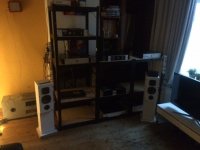
Jow members, afther a long time waiting i want to task weither somebody has schematics for a 3 pair MONO amplifier to fit in the enclosure as photos below.
On www.buildaudioamps.com there is this project, except it has not been released yet.

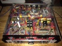
The transistors, 12 in total, are the MJ2955 and the 2N3055

Now i am using this schematic from www.sound-au.com, and of course it works fine.
And have left 1 pair on each amplifier not connected.
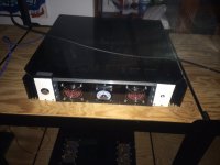
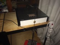
In the middle there is the power supply with 2 toroidal transformer it, for a separate 35VDC in total of 340VA power supply. Picture IMG_1081.JPG IMG_1079.JPG
Looking for a higher quality amp, to replace it.
Question: Does anybody know a website for a amplifer schematic to exactly fit in this enclosure ?
If not with 3 pairs on each side, but maybe with 2 ?
Thanks Greets, Wouter van Wegen
woutervanwegen@gmail.com
PS: There are PowerCON cables and XLR cables between the power supply in the middle and the 2 amps. On the left and right side.
On www.buildaudioamps.com there is this project, except it has not been released yet.
The transistors, 12 in total, are the MJ2955 and the 2N3055
Now i am using this schematic from www.sound-au.com, and of course it works fine.
And have left 1 pair on each amplifier not connected.
In the middle there is the power supply with 2 toroidal transformer it, for a separate 35VDC in total of 340VA power supply. Picture IMG_1081.JPG IMG_1079.JPG
Looking for a higher quality amp, to replace it.
Question: Does anybody know a website for a amplifer schematic to exactly fit in this enclosure ?
If not with 3 pairs on each side, but maybe with 2 ?
Thanks Greets, Wouter van Wegen
woutervanwegen@gmail.com
PS: There are PowerCON cables and XLR cables between the power supply in the middle and the 2 amps. On the left and right side.
Attachments

Last edited:
The SC-480 is a classic and fun circuit.
There is many suitable replacement transistors for what is being used
But the overall design is rather simple and straight forward.
I would use MJE243/253 instead of the 340/350
BC639/640 could be replaced with higher voltage 2n5551/5401
BC557 could be used on input, or another common low noise transistor with higher voltage be KSA992
SC-480
Believe Elector magazine had it appear original in December 1976
But Silicon Chip did a follow up in January 2003
Using 2955's and 3055's at rail voltages of ±40 Vdc appears to be somewhat brave 😳!
Best regards!
Best regards!
I only got + and - 35V afther rectifier
And some old toroidal transformer for +and - 50V, afther rectifier
I am still browsing www.elcircuit.com
Anybody got more options in the mean while ? Greetz Wouter
And some old toroidal transformer for +and - 50V, afther rectifier
I am still browsing www.elcircuit.com
Anybody got more options in the mean while ? Greetz Wouter
+/_ 35 volts is lower voltage
and better for output devices being used.
there is likely hundreds of designs in the 60 to 120 watt zone
where rail voltage on the schematic is going to be 32 to 42 volts
but you would power it with the supply you have.
there is countless designs with maybe only 1 or 2 pairs of output devices
in your case if you wanted 3 outputs
you just need to make sure the driver transistors are suitable to drive 3 devices.
not very hard since the more common used driver will be MJE15032/33
or many other voltage ratings in that family of transistors.
basically Q8 / Q9 would need to a higher wattage package to push 3 devices.
and the 100 ohm emitter resistors be lowered for the right amount of current.
pretty normal to leave the PTC out of the circuit.
most should recognize the topology from hitachi/maplin fame
but changed over to thermal track BJT outputs.
very respectable distortion ratings for being such a simple circuit
“Pushing” three output devices isn’t necessarily any harder than “pushing” two. Pushing 4 ohms load instead of 8 is. If you were pushing 4 ohms and went from two output devices to three the load on the drivers may actually come down because output transistor hFE will be higher due to the lower peak current in each. When you push lower impedances, regardless of the number of output devices, then you think about beefing up the drivers.
yes understood. good point...but
if I posted a schematic with a T0-126 package pushing 3 2n3055
I already know the flame war that would erupt.
if I posted a schematic with a T0-126 package pushing 3 2n3055
I already know the flame war that would erupt.
Im sure he might find something in the Elcircuit worm hole
but there is likely something in many old Elector Magazines or Silicon Chip
Paul Kemble's
Website is always a fun read, mainly vintage amplifiers and inspiration for new designs.
2N3055/ MJ2955 has a vintage feel to it anyways.
T03's are fun
Maybe something with a Triple Output topology or a Locanthi T topology
Last edited:
True, I did use TIP31’s in my prototype - but the point of that exercise was to see what could be done without using “good” transistors. A pair of modern sustained-beta drivers (in TO-126) would have worked, perhaps “better” - without the need for an output triple. When you can find good driver transistors, you can usually do better than 3055’s for outputs. It is often a fun and enlightening exercise to see what can be done with junk. At one time, salvage was the only way. 20 years from now we may very well be back to that when all the good high performance stuff is out of production.
- Home
- Amplifiers
- Solid State
- 3 pairs TO-3 amplifier to fit in enclose as photo attachments