So I saw this post from Mr Pass
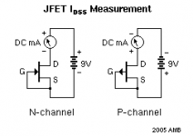
I'm assuming this is for N-channel and to test for P-channel, I just need to reverse power supply polarity. Am I right?
Thanks
Get a 5 to 13 volt supply and a DC voltmeter. Connect the +V to the
Drain, connect the Gate and Source together to a 100 ohm resistor,
and connect the other lead of the resistor to ground.
Measure the voltage across the resistor, which gives the Idss. 1 volt
= 10 mA of current.
Try to measure all devices under the same conditions, temperature,
and duration of test.
I'm assuming this is for N-channel and to test for P-channel, I just need to reverse power supply polarity. Am I right?
Thanks

That.
The 100 ohm resistor just provides us for an easy way to measure current by turning it into easier to measure voltage.
Just in case you wonder why no 100 ohm resistor is shown on Adason´s schematic.
The 100 ohm resistor just provides us for an easy way to measure current by turning it into easier to measure voltage.
Just in case you wonder why no 100 ohm resistor is shown on Adason´s schematic.
Thanks everyone. I just checked my meter and voltage measurement is more accurate than its current measuring capability. I'll use the one with resistor.
Some FETs may have a high Idss and testing that could over-dissipate the device if the testing takes too long to do. In that case, the test would be done using a short duration on-time pulse and capturing the resultant current across, say, a sense resistor, on a scope.