Hi all.
Hope somebody can help.
I have a Quad 303 which was faulty but i've fixed the fault ( open cct resistor ) and I intend to make 2 new amplifier boards and PSU board from scratch with HQ components throughout. Im puzzled by the schematic for the 303 and the actual board ? - The schematic shows 4 diodes around transistors tr103 and 104, but the actual amplifier has only 2 diodes ? I havent as yet verified why there are only 2 diodes fitted , but I will trace the tracks - any ideas what s going on with just the 2 diodes. Thanks . attached is a portion of the schematic im talking about. this has been posted in other sections of the forum, apologies if this offends ?
Attachments
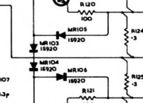
There are many versions of the 303. If you only have two diodes, then it sounds like it uses a vbe multiplier rather than diode biasing. The two diodes here play no part in the normal operation of the amp and only come into play under adverse operating conditions. The extra diodes in yours are in place of the multiplier.

Thanks for the reply, I'll open it up again this afternoon and check the pcb against the schematic. I d/loaded all versions from the DADA site and I can then compare. What you have said makes perfect sense looking at the diagram you have kindly attached . I'll keep in touch - Adrian