Background
I have a pair of FA123s that I no longer use. One of them has an issue I can have Hypex address, but I have another thought.
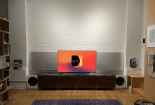
I'd like to repurpose the components of the FA123s in support of extending my home theater audio system (see attached image).
I have two stereo NCore amps that I use with a miniDSP device to integrate DML panels and woofers that serve as left and right front speakers.
I have additionally turned my LG OLED TV into a center channel speaker by attaching an exciter to it.
I have smaller DML speakers to serve as rear left & right channel speakers.
I have an A/V pre-processor that has the capacity to do the room equalization I may need.
I need amplifiers for the smaller DML rear left & right speakers and the center channel speaker.
I can use the working FA123 for the center channel, but this seems too much of a device for the purpose.
Additionally, as I would use RCA analogue out from the A/V pre-processor to the FA123, the FA123 would first do an ADC (analogue to digital conversion) make the digital available for DSP, then apply its DAC to return analogue output to the center channel speaker.
The FA123 does much more than I need.
This said, the FA123s's NCore amps - on their own - could prove a great match for my application.
Question
Could I repurpose any of the components of these FA123s?
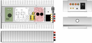
I could have all the following wrong (see attached image) ...
The 100w amp appears to sit on a discreet board and receives power from the power supply mounted on the board holding the two 125w amps.
I don't need the DSP | DAC functionality.
Would the following work for the center channel amp?
I know I can purchase 2 or there UcD180HG with HxR from Hypex and put something together, but I really don't need 180 watts per channel.
These FA123s have served me very well across a number of different systems, I'd love to give them another life.
Any thoughts appreciated.
I have a pair of FA123s that I no longer use. One of them has an issue I can have Hypex address, but I have another thought.
I'd like to repurpose the components of the FA123s in support of extending my home theater audio system (see attached image).
I have two stereo NCore amps that I use with a miniDSP device to integrate DML panels and woofers that serve as left and right front speakers.
I have additionally turned my LG OLED TV into a center channel speaker by attaching an exciter to it.
I have smaller DML speakers to serve as rear left & right channel speakers.
I have an A/V pre-processor that has the capacity to do the room equalization I may need.
I need amplifiers for the smaller DML rear left & right speakers and the center channel speaker.
I can use the working FA123 for the center channel, but this seems too much of a device for the purpose.
Additionally, as I would use RCA analogue out from the A/V pre-processor to the FA123, the FA123 would first do an ADC (analogue to digital conversion) make the digital available for DSP, then apply its DAC to return analogue output to the center channel speaker.
The FA123 does much more than I need.
This said, the FA123s's NCore amps - on their own - could prove a great match for my application.
Question
Could I repurpose any of the components of these FA123s?
I could have all the following wrong (see attached image) ...
The 100w amp appears to sit on a discreet board and receives power from the power supply mounted on the board holding the two 125w amps.
I don't need the DSP | DAC functionality.
Would the following work for the center channel amp?
- RCA analogue inputs.
- Binding posts for speaker wire.
- Add an appropriate power supply for the 100w amp.
- Supply mains connection.
- Put in in a box.
I know I can purchase 2 or there UcD180HG with HxR from Hypex and put something together, but I really don't need 180 watts per channel.
These FA123s have served me very well across a number of different systems, I'd love to give them another life.
Any thoughts appreciated.
Attachments

More detail...
The FA123s use the Hypex NC-MP122 "mains" modules.
I still have to figure out which "pins" to use to get them to work without the DSP | DAC module from the FA123s.
Any thoughts appreciated.
Working plan for the build attached. Pretty straight forward:
Another requirement has developed as I don't have a good way to "hide" speaker cable or interconnects to the surround speakers.
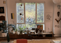
(Note: I've constructed the current version of the DMLs for the surround speakers with Dayton Audio Thrusters mounted on foam core. You can see them on either side of the window in my first post.)
Ideally, I'd like to add an ethernet port and whatever else I need to "network" the amp build.
I will then need to add something (probably an external box) to connect my A/V pre processor to the network as well.
Given its location in my loft, I'll probably need to use some wifi module of some kind.
Does anyone have suggestions?
The FA123s use the Hypex NC-MP122 "mains" modules.
I still have to figure out which "pins" to use to get them to work without the DSP | DAC module from the FA123s.
Any thoughts appreciated.
Working plan for the build attached. Pretty straight forward:
The FA123 front plate (cut down a bit) as the bottom of the case.
A pair of 12" heat sinks from HeatSinkUSA as the sides.
Aluminum plates (or something) for the top, front, and back.
Another requirement has developed as I don't have a good way to "hide" speaker cable or interconnects to the surround speakers.
(Note: I've constructed the current version of the DMLs for the surround speakers with Dayton Audio Thrusters mounted on foam core. You can see them on either side of the window in my first post.)
Ideally, I'd like to add an ethernet port and whatever else I need to "network" the amp build.
I will then need to add something (probably an external box) to connect my A/V pre processor to the network as well.
Given its location in my loft, I'll probably need to use some wifi module of some kind.
Does anyone have suggestions?
Attachments
Many thanks.
That helps a lot!
I figured someone must have tried this.
Can I trouble you for a few (hopefully) quick questions | clarifications.
In the screen shot of the photo you posted, you have what looks like two wires connecting the b1 with kong triode board to a pin socket on the NC-MP122.
This seems like line out to the NC-MP122, essentially what I want to connect from my proposed amps RCA unbalanced inputs to the amp board.
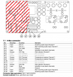
From the operating manual for the amp (see attached screed clip) it looks like you've connected to the J4 H-Box.
My first tine around with these connectors.
If I follow the manual, it seems like I'll need to connect my RCA inputs to at least two (but maybe all 4)of the following pins:
Channel 1: J4.1 or J4.2
Channel 2: J4.15 or J4.16
Which pins did you connect to on the amp board?
Did you repurpose the connector from your FA122?
If so how?
Else, where can I get one of these H-Box connectors and instructions for DIYing | using them?
Again, many thanks.
- Andreas
Attachments
Last edited:
From memory (the amp and my notes are up in the loft), each channel's input went between GND and the non-inverting input, so J4.2 and J4.15. I left the inverting wire connected to the Hypex module but didn't connect it at the preamp end, just in case. Yes, I used the existing wiring and connectors, just cutting out the sections of the ribbon cable I didn't need. Also remember that there are two pins on J6 that need shorting together to bring the module out of standby. In my case I ran these to a switch on the front panel to allow the preamp to power-up before switching on the power amp. Hope this helps.

More than helped.From memory (the amp and my notes are up in the loft), each channel's input went between GND and the non-inverting input, so J4.2 and J4.15. I left the inverting wire connected to the Hypex module but didn't connect it at the preamp end, just in case. Yes, I used the existing wiring and connectors, just cutting out the sections of the ribbon cable I didn't need. Also remember that there are two pins on J6 that need shorting together to bring the module out of standby. In my case I ran these to a switch on the front panel to allow the preamp to power-up before switching on the power amp. Hope this helps.
You've officially risen to the heights of a diyAudio (internet) angel in my estimation.
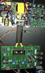
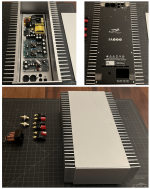
Making some progress on this amp build. See attached.
I had almost everything on hand.
I used the FA123 face place as the bottom of the chassis, cutting off the bit I didn't need.
The amp boards screw into the same place they did before I repurposed the FA123.
The attached image shows the smaller 100w amp board mounted, but I don't know that I'll leave it.
Still looking for a wifi board so I could send line audio to the amp wirelessly.
I cut top, back, and sides from the aluminum cover of an old Apple Mac Pro server I had on a shelf.
Needs some finishing, but it should look OK.
I attached all the pieces (excepting the top) with VHB tape. Takes careful alignment, but has great (Very High Bond) strength.
I may not need to screw it together.
Next, I'll mount everything to the back plate and start to wire everything.
The build would benefit from a led on the front panel. I need to see what I have.
Attachments
@Logic800...Also remember that there are two pins on J6 that need shorting together to bring the module out of standby. In my case I ran these to a switch on the front panel to allow the preamp to power-up before switching on the power amp.
I've read through the NC122MP manual, but haven't found explicit directions as to which "two pins" on J6 "need shorting".
I also tried to make out what pins you shorted from the photo you posted at: https://www.diyaudio.com/community/threads/my-hypex-amp-with-b1-with-korg-triode.343111/.
My best guess so far:
J6.3 Output - Vaux,standby - Regulated standby supply) and
J6.9 Input - PS Enable - Power supply enable.
Everything else all hooked up and ready to go.I admit to not having a lot of confidence in my guess.
Clarification appreciated.
Attachments
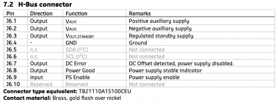
yes, short J6.3 and J6.9 and it will power up
I would use unbalanced to balanced cable, mening that I will connect one channel to J4.1/J4.2/J4.3 to the board and on unballanced side connect CH1 In - to GND
as on this picture
http://www.douglas-self.com/ampins/balanced/XLRphono2.gif
You could add led and connect it to J6.1 to J6.4 and place some resistor, like 10K in series with led (try some other value to get results that you like)
Last edited:
- Home
- Amplifiers
- Class D
- Repurposing Hypex FA123 components