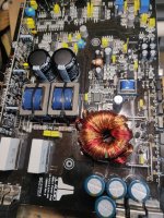
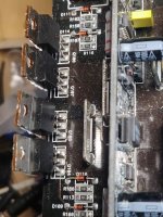
Good Day. This JL Audio A1400 powers up in protection mode with 9.9v on the speaker + terminals. The listing below is the voltages on the output transistors (IRF540):
Location / Gate / Drain / Source
Q106 / 12.2v / 83mv / 83mv
Q107 / 83mv / 71v / 83mv
Q105 / 83mv / 9.9v / 83mv
Q104 / 9.9v / 71v / 9.9v
The 12.2v on the gate of Q106 is a little concerning. All of the outputs test good in the board. Wondering if the AHC132s on the output driver board are damaged but just decided to post for help before I start to remove stuff...
Attachments
If you pulse the remote (quick on/off), do you get about 15 seconds of the low-voltage power supply running?
Start with the low-side gate terminal for the outputs. If the scope is grounded to your 12v power supply, you don't need anything else.
Not sure what I should be seeing on the output gates but there are no waveforms. Gates of Q104 and 106 deflect upwards for 14-15 seconds when the remote is pulsed. The output is a solid line, no waves at all unless it is turned down to nanoseconds per division.
- Home
- General Interest
- Car Audio
- JL Audio A1400D in protection