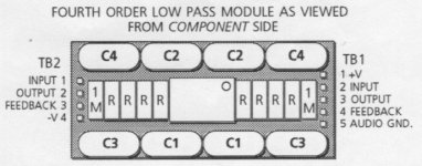
Hi, my active crossover, a/d/s/ 642ix, can only be adjusted filter frequencies by changing filter modules. It has instruction for modifying these modules. They also had provided table of modified values. Please find attached pictures. I’d like to have the low-pass filter frequency to be at 320 Hz. Please help me to calculate component values to achieve 320 Hz. Thanks in advance
Attachments
Have a look down this page at active filters: http://sim.okawa-denshi.jp/en/Fkeisan.htm see if there's any that match your design.
(sorry for the short answer - just noticed it before switching to work)
(sorry for the short answer - just noticed it before switching to work)
Last edited:

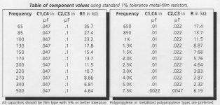
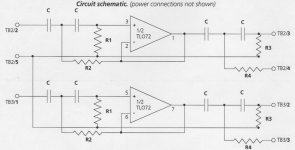
R1 Value for 320Hz is 6.81* 340/320 = 7.24k which isn't an E24 value. You could put 7k5 in parallel with 200k which will be close enough given the cap tolerances.
Sorry, but is it as easy as simply using the rule of three?
I tried applying the rule of three on the other values in the table, and found they weren’t linear relationships, constant slope when plotted graphs. However, I’m not sure about my math.
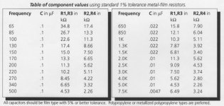
If you do some quick math on the table you've shown, you'll see the product of the frequency (first column) and the R1 value (right column) is a constant, around 2320 give or take a few dozen. I used that relationship to calculate the 320Hz value. You can double check because there are 150 and 170Hz values in the table which if you interpolate between them gives 160Hz. And that's half the frequency you want, hence has double the R1 value you're looking for.
If you do some quick math on the table you've shown, you'll see the product of the frequency (first column) and the R1 value (right column) is a constant, around 2320 give or take a few dozen. I used that relationship to calculate the 320Hz value. You can double check because there are 150 and 170Hz values in the table which if you interpolate between them gives 160Hz. And that's half the frequency you want, hence has double the R1 value you're looking for.
That’s clear. Big thanks to you.
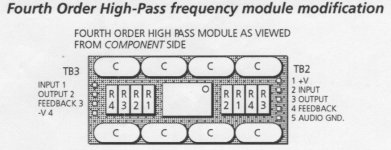
Let me ask another final question. This is slightly more difficult. Please find attached again. This is the high-pass filter. I would like 540 Hz on the high-pass filter. But it has various C values. I’m not sure if I should use 0.1 or 0.022 uF. Please assist me one more time.
Attachments
Last edited:
Given that 540Hz is between the two tables and the cap value jumps down by a factor almost 5X, I'd go for a cap value of 0.047uF to create the 540Hz turnover frequency. Lower resistor values are less noisy but too low is going to load the driving stage so something in the region of 10k would be fine.
With the cap at 47nF, extrapolating from the left table gives 8.9k for R1,R3 at 540Hz and 4.46k for R2,R4. So 9k1//470k and 4k7//91k.
With the cap at 47nF, extrapolating from the left table gives 8.9k for R1,R3 at 540Hz and 4.46k for R2,R4. So 9k1//470k and 4k7//91k.
- Home
- Source & Line
- Analog Line Level
- Help me with this active filter modification