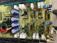
I received this amp which has been through the repair ringer - looks like previous repair was a frantic non-complete job.
I saw one of the ANW7 modules had been cut and so I replaced both modules with discrete components. The amp powered slightly with only 0.15A draw, though the PS was producing and amp had +-17v Rail.
No regulated voltage.
I then replaced both 470uf 16v caps with new 25v units in the regulated side, and the amp powered produced +-17v rail and +-16v regulated, draws 1.1A and passed audio unloaded. Right channel passed audio under small 4-ohm load. As soon as I put a small 4-ohm load on the LEFT channel the amp went into protect.
From that point, I could no longer get the amp to produce regulated voltage.
I then replaced several other caps as well as rebuilt the two ANW6 modules. I also replaced R4 and R5 with 1kohm units but still no regulated voltage. R4/R5 are connected directly to rails and are servicing the regulated voltage supply to the 470uF caps... Theres only about +-0.3v on the regulated side of these resistors.
I checked everything I could - again this amp has some service wear from tech troubleshooting so - it could be anything.
Any thoughts?
Photo one moment

pulled Q4 mpsa14 and the amp passes audio.
What’s Q6 supposed to be? BC639 is installed never seen one of those in these amps.
What’s Q6 supposed to be? BC639 is installed never seen one of those in these amps.
Q6 center leg is connected to the +16v side of R4
Pulling Q6 with Q4 installed and amp does not produce regulated voltage.
Pulling Q6 with Q4 installed and amp does not produce regulated voltage.
In many other ZED amps, the mute delay is produced by having a 2061 transistor pulls the ±16v supplies (fed by resistors) together. The rail voltage isn't affected by that delay.
If there is no transistor pulling ±16v together (leaves the preamp voltage at about 0v), this amp is different.
If there is no transistor pulling ±16v together (leaves the preamp voltage at about 0v), this amp is different.
R4 and R5 connect to Q6 Emitter & Collector.
OK so now Im thinking the amp just isn't producing enough rail voltage which in turn may be causing the amp to stay +-16v muted (possibly).
OK so now Im thinking the amp just isn't producing enough rail voltage which in turn may be causing the amp to stay +-16v muted (possibly).
Look at the 66p2.gif image in the autotek folder. The circuits may be the same. Follow the circuit back to see if you can find the fault.
Q4 on this board is similar to Q2 in that image.
With Q4 removed, the amp passes audio, but also the amp's power AND protect LEDs are on.
IC3 on this board is IC7 on this amp.
IC3 LM358
1: 3.51
2: 8.85
3: 3.323
4: 4.21
5: 8.9
6: 12.5
7: 3.7
8: 13.6
I would have thought pin4 would be 0v but its not. Pin 4 is connected to C6(Or C5), THERM, and NW4 per the 66p image.
What does the upside down T mean on the image? Are all those connected - TL594 pin7, IC7 pin4, and Q2 emitter?
Is there an open trace between pin 4 and ground? The items you mentioned are all supposed to be connected to ground.
OK I think I fixed the amp. All components installed. I believe the amp was missing a ground jumper to the LM358 pin4 IC. Possibly previous tech removed it? Or a broken trace somewhere? The following were isolated:
C5/THERM/NW4/LM358(Pin4) <-- All these were connected, but none of these were connected to ground.
Installed a 4" jumper and the amp powered with Q4 in!
Thanks for the schematic link
C5/THERM/NW4/LM358(Pin4) <-- All these were connected, but none of these were connected to ground.
Installed a 4" jumper and the amp powered with Q4 in!
Thanks for the schematic link
- Home
- General Interest
- Car Audio
- Rodek 2150i no regulated voltage