Hello,
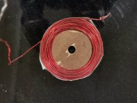
1)I'm building a crossover and have some inductors that have too much inductance. I need (6) 6.6 mH which are kinda pricey for air core. I unwound a couple 9s to 6.6 mH. When I was unwinding them, some of the enamel has come off the wires as pictured. Should I apply some sealant on these coils?
2)Additionally, I have (2) 15 mH coils that I want to use to get the other 4 coils I need. When I unwound the 9 mH, I just let the wire lay on the floor and kept measuring until I came to around 7 mH before I cut it and then continued to 6.6 mH. Since I want to reuse the wire, I want to wind it up on a spool as I unwind it. I should be able to get pretty close by measuring the diameter of the coil as I unwind it, since I won't be able to measure inductance as I'm making a new coil as I unwind it. Can I scrape off some enamel and measure when I get close and not be concerned?
3)It's the last 2 coils I'm worried about. Since I'm fairly certain I won't be able to wind them as tight, I will use more wire and have more resistance. I'm already at 1.5 ohms on the 6.6 mH coils. Additionally, I will have a spool of wire that the enamel is compromised on from unwinding it. This concerns me as well. There is no specification for inductor resistance in the crossover, but I thought I was supposed stay under 1 ohm and preferably .5 ohm.
Thank you
You will need to keep the tension on the accepting/increasing spool tight. I would keep the donor coil on the floor between your feet with tension, and wind it up by hand, unless you have a jig or winder.
Scratching enamel off to get a reading is okay periodically, as the next layer will just cover it up with enameled wire. If it suits you, and you want to, just apply electrical tape over the spot and keep going- but it's not totally necessary.
I would keep a strong piece of tape handy, or an office binder clip at the ready for when you pause and check to hold the wire in place for the time being.
Lastly, zip tie or tape your coils when finished and if able dunk them in polyurethane and let them dry. This will bond the loose and scraped portions internally to make it a more solid structure.
As to the removal of enamel on the pictured coil, if you cannot get a continuity reading from what you think is exposed copper to another winding, I wouldn't worry about it. A lot of times, the unwound coils have it only on the surface, and not in between where that affects value. If you do get a reading, and it is not just the first layer of coating that has come off (enamel wire usally is double coated, some grades are better than others), then taping or dunking can finalize it as it sits.

There's the wire coating, an example would be polyurethane.. and then there's the inductor potting, an example might be varnish or similar.some of the enamel has come off the wires as pictured
Polyurethane wire coating can be quite durable. While this isn't for a high Voltage application where it is critical, still a shorted turn would be a bad thing perhaps rendering the inductor ineffective.
It may be ok, can you simulate it...I thought I was supposed stay under 1 ohm and preferably .5 ohm.
Thanks. You have given me the confidence to do it with success. With some patience, I might be able to wind and unwind at the same time. I ordered this budget coil winder.
Upon closer inspection with a magnifying glass, it appears the polyurethane coating got scruffed up when I pulled it apart, not the red insulation.There's the wire coating, an example would be polyurethane.. and then there's the inductor potting, an example might be varnish or similar
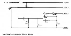
I am not versed in SPICE if that's what you mean. I am copying a crossover. I've built it once already. It's pretty good. I am going to build it again using different capacitors and air core inductors and see if I can hear any difference. I used the cheapest cored inductors I could find and Solen and Clarity poly capacitors. I'm wondering if it's going to be more pleasant with air core inductors and MBG0-2 capacitors.It may be ok, can you simulate it...
Attachments
Spice might be used, especially if you can apply the varying impedance of the drivers. A crossover simulator would be good choice.
In your case you're curious about the difference in response the inductor resistance will cause. What you say about keeping the resistance low is a rule of thumb, it matters to differing degrees in different situations.
In any case, if you want to make direct listening comparisons then you should add a small resistor where necessary to ensure it's the same when you change inductors.
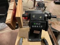
I received the coil winder and unwound/wound the inductor. While I wound it 3 times to get a factory finish,in the end it turned out about the same as the first one. The crank on the winder seems too short. I put some oil on the gears and it only helped a little. (The placard fell off while I was unboxing)
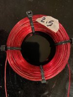
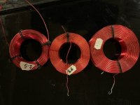
I unwound the 15 mH inductor to 6.6 mH and used the remaining wire to wind my coil. It ended up being 2.5 mH w/.9 resistance. I only got 211 turns out the remaining wire whereas the 6.6 mH inductor has around 350 turns.
With a motor or some more cranking power, I could get it looking better. The wire also got bent up unwinding, so that didn't help. Not a horrible result, but I still need a couple 6.6s 🙂 . You can see in the pictures the cores look different. The 15 and 6.6 are the same size and the one I wound is only slightly bigger. It's the closest sized hole saw I had.
Attachments
-
 !cid_e21ba78b-f7ad-46b4-ae74-3c1a77ce4140@namprd20_prod_outlook.jpg86.2 KB · Views: 74
 -
 !cid_b4c8220f-3757-4628-8fc7-c2733414d895@namprd20_prod_outlook.jpg56.5 KB · Views: 76
 -
 !cid_b65bcc3d-de83-48ea-baf8-c66ce454d5bb@namprd20_prod_outlook.jpg57.4 KB · Views: 69
 -
 !cid_61b49a53-e02c-4539-a8b8-523340ae3445@namprd20_prod_outlook.jpg48.6 KB · Views: 80
- Home
- Loudspeakers
- Multi-Way
- Unwinding/Rewinding inductors