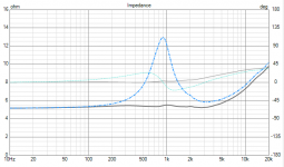
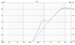
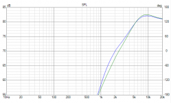
So can people please advise on the implications of running a driver be it woofer or mid or tweeter or compression driver at its resonant frequency
Just trying to learn further and understand so a few questions please
A driver Driven at its resonant frequency give or take +/-
1 Can or will damage be expected provided it receives low voltage and not overdriven in excess
2 if the driver been driven encounters higher dB feedback will an amplifier compensate re damping..?.
3 same question as number 1 and number 2 ..but if it was a compression driver would things be different as compression drivers can go low but with higher sensitivity ie 106db vs 85db etc
So in a nutshell can a sustained frequency be amplified without redress.
There’s got to be advantages or disadvantages of doing this thoughts please
4 Can the resonant frequency of any driver be found without parameters ie frequency sweep multimeter
Last edited:
Seems to me that most run their midWoofers at resonance, if you watt the FR to be flattish at the resonance peak you have to consider the Rout of the driving amplifier
As to the resonance it is fairly easy to measure, but it can move depending on the power used to measure
dave
As to the resonance it is fairly easy to measure, but it can move depending on the power used to measure
dave
No. In any case, tweeter resonance is always driven.. even if generally at some lower level in the rolloff region. Of course if you cross first order within the octave of resonance then you won't get too much useful output. There are better ways to use a 1" dome.1 Can or will damage be expected provided it receives low voltage and not overdriven in excess
It doesn't work like that.2 if the driver been driven encounters higher dB feedback will an amplifier compensate re damping..?.
Often used lower than resonance in a domestic situation.but if it was a compression driver
Impedance sweep.4 Can the resonant frequency of any driver be found without parameters ie frequency sweep multimeter
Just insert a series resistor (around 1k) for the frequency sweep, and the resonant frequency will be evident.Impedance sweep.
Faking a current amp with a voltage amp. I have a current amp Duo built for the purpose. WT2 comes with a little current amp. I suspect one of the reasons I find their SW the most useful cheap tool for diyersa series resistor (around
dave
It's acoustical output is increased at the same time as the input power is decreased.
Fun eey!
//
Fun eey!
//
A tweeter can be used down around its resonance if you apply a parallel LCR trap right at Fs. The problem is Fs can change with temperature and break in, so its important to run the driver for a while and then measure Fs to calculate the LCR impedance notch. The other issue is power handling and driver xmax, usually making it a pointless exercise. I always use an LCR notch if the tweeter will be run on a first order HP.
When you drive a driver at Fs two things happen.
The first is that efficiency goes up. Back EMF causes impedance to rise. When input voltage remains constant and excursion too, this amounts to more output for a given power input.
The second is that the origin of distortion product shifts from the electrical to the suspension side. In the region outside the resonance region, cone movement is largely determined by current flowing through the voice coil. So any distortion here, like Bl modulation, will have a relatively large impact. At resonance, much of the motion is determined by inertia of the moving mass versus mechanical storage in the spring system formed by the suspension, counteracted by breaking forces. So any non linearities here will determine distortion in cone movements.
Since it is even more difficult to reduce non-linearities on the mechanical side than on the electrical side, all drivers I know show increasing distortion going towards resonance.
Note 1: some breaking forces such as eddy currents in aluminium voice coil formers are based on electrical phenomena. Best avoid those for best sq.
Note 2: mechanical non-linearities can only affect distortion by detracting energy from the resonant system. Hence the goal to increase Qms as far as possible. A high Qms is a measure for low friction. No friction, nothing detracted from the resonant system, no distortion.
Last edited:
Some of my favorite tweeters use aluminum formers. I used to be hung up about this but came to the conclusion it doesn't make as much difference as I originally thought. I have a few HF drivers with Ti, fiberglass and nomex formers which sound great too, but not in any significantly way more than ones with Alu formers. For instance, the Audax TW025A28 is an amazing dome, having an Alu former and its my favorite 25mm dome by a mile. The Alu former also has the benefit of increased power handling and its stiffer than kapton (used alot for tweeter VC former material).Since it is even more difficult to reduce non-linearities on the mechanical side than on the electrical side, all drivers I know show increasing distortion going towards resonance.
Note 1: some breaking forces such as eddy currents in aluminium voice coil formers are based on electrical phenomena. Best avoid those for best sq.
- Home
- Loudspeakers
- Multi-Way
- What happens when you run a driver at it’s resonance frequency


