A friend gifted me this antique ham radio rig several years ago. It has been stored at home by those years, more. It is dated about the early 70's.
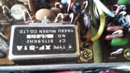
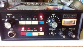
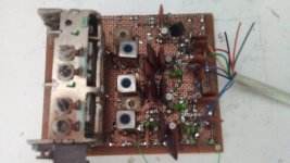
I restored it and modified it replacing several of the BJT's in the signal path and crystal oscillators enhancing the sine wave by them generated and reducing the noise and a slightly increase in its sensitivity. Note that this set ISN'T A HIFI DEVICE. It has been designed for ham radio use mainly, as a SSB (Single Side Band) or CW (Morse code) and the audio BW is severely reduced in order to limit the RF BW thus increase the number of channels in a ham band and concentrate the output power in only one of the dual AM sidebands. The unwanted sideband and the carrier is eliminated increasing the overall efficiency. Audio BW is restricted to spoken words and is from 300 to 3000Hz at best. A powerfull crystal filter is included at the IF stage to cancell out the unwanted SB and the carrier at TX and reducing the noise at RX. Unfortunatelly one of the front knobs was lost prior to own it.
Already I posted here the modification of the audio amplifier inside the rig and replace the original AN214 (burnt) with a pushpull of 2SK941 small power MOSFET's.
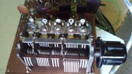
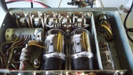
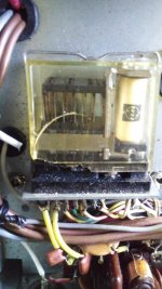
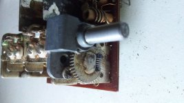
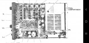
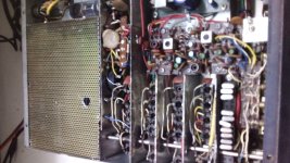
The tube final power amplifier is still inoperative. I need to build a multivoltage power supply including 250V for the 12BY7, about 500V for the 6DQ6's plates (paralleled), regulated 150V for 12BY7 & 6DQ6's screens and -100V for the biasing of the grids. The relay below depicted switchs the antenna to RX or TX stages and simultaneously maintain both grids bias well below the cutoff level in order to avoid interference in RX and tubes overheating. The front panel includes a switch that power up the heaters if it is wanted to transmit.
Originally the rig has 3 crystal channels per ham band although only one was provided by factory, installed. There is a switch that enables a rear input for an external VFO (Variable Frequency Oscillator), a means to cover the wide of each ham band.
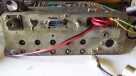
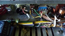
The rear connectors are obsolete and difficult to find. So they were removed and replaced with commonly available ones. One of them has a free contact to ground in common to the band selector, on each band which enables an external power amplifier or VFO to act in synchronizity with the rig and a free changeover from the TX/RX relay. This has been replaced by a sub D 9 pin unit, and as I win some free pins, I hook a regulated 9V to it to power the VFO stage alone. The input of the external VFO now is carried by means of a DIN connector 5 pin where I added a 12V out for the VFO amplifier and adder. The jack for the CW key was removed as I hate Morse code, and in its place, a 100K pot is fitted to ajust externally the mic gain. Such a control was inside the mic amp and not available for the user. A 3.5mm mono jack was added too to use an external speaker, not included in the cabinet. A speaker terminal was included in one of the changed connectors but I prefer it separately.
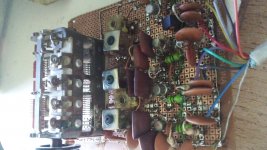
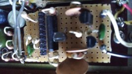
I designed my own VFO using the 3 FM sections of it for each ones of the 3 Clapp oscillators made about 3SK40 dual gate MOSFET's. The rig is so designed that with 3 oscillators it can cover 5 bands, sharing part of the oscillators for two bands. A secondary winding in each oscillator coil (made inside of new TOKO 10mm cans) are serial wired and added to feed a 4th 3SK40 that decouples the oscillator from rig and the cable linking them. Each source is choosen by the connections in the 9 pin connector above mentioned. The 2nd gate of all MOSFET are all tied together to a voltage divider giving them about 4V stabilized, the point where usually those devices gives its best transconductance. There isn't risk of oscillator's mutual interference as only one of them is powered at a time.
The schematic of the entire apparatus, is of course, very large and available in the web in the scans of the original user manual. Those for the VFO, PSU and for the audio amp will be available soonly.
I restored it and modified it replacing several of the BJT's in the signal path and crystal oscillators enhancing the sine wave by them generated and reducing the noise and a slightly increase in its sensitivity. Note that this set ISN'T A HIFI DEVICE. It has been designed for ham radio use mainly, as a SSB (Single Side Band) or CW (Morse code) and the audio BW is severely reduced in order to limit the RF BW thus increase the number of channels in a ham band and concentrate the output power in only one of the dual AM sidebands. The unwanted sideband and the carrier is eliminated increasing the overall efficiency. Audio BW is restricted to spoken words and is from 300 to 3000Hz at best. A powerfull crystal filter is included at the IF stage to cancell out the unwanted SB and the carrier at TX and reducing the noise at RX. Unfortunatelly one of the front knobs was lost prior to own it.
Already I posted here the modification of the audio amplifier inside the rig and replace the original AN214 (burnt) with a pushpull of 2SK941 small power MOSFET's.
The tube final power amplifier is still inoperative. I need to build a multivoltage power supply including 250V for the 12BY7, about 500V for the 6DQ6's plates (paralleled), regulated 150V for 12BY7 & 6DQ6's screens and -100V for the biasing of the grids. The relay below depicted switchs the antenna to RX or TX stages and simultaneously maintain both grids bias well below the cutoff level in order to avoid interference in RX and tubes overheating. The front panel includes a switch that power up the heaters if it is wanted to transmit.
Originally the rig has 3 crystal channels per ham band although only one was provided by factory, installed. There is a switch that enables a rear input for an external VFO (Variable Frequency Oscillator), a means to cover the wide of each ham band.
The rear connectors are obsolete and difficult to find. So they were removed and replaced with commonly available ones. One of them has a free contact to ground in common to the band selector, on each band which enables an external power amplifier or VFO to act in synchronizity with the rig and a free changeover from the TX/RX relay. This has been replaced by a sub D 9 pin unit, and as I win some free pins, I hook a regulated 9V to it to power the VFO stage alone. The input of the external VFO now is carried by means of a DIN connector 5 pin where I added a 12V out for the VFO amplifier and adder. The jack for the CW key was removed as I hate Morse code, and in its place, a 100K pot is fitted to ajust externally the mic gain. Such a control was inside the mic amp and not available for the user. A 3.5mm mono jack was added too to use an external speaker, not included in the cabinet. A speaker terminal was included in one of the changed connectors but I prefer it separately.
I designed my own VFO using the 3 FM sections of it for each ones of the 3 Clapp oscillators made about 3SK40 dual gate MOSFET's. The rig is so designed that with 3 oscillators it can cover 5 bands, sharing part of the oscillators for two bands. A secondary winding in each oscillator coil (made inside of new TOKO 10mm cans) are serial wired and added to feed a 4th 3SK40 that decouples the oscillator from rig and the cable linking them. Each source is choosen by the connections in the 9 pin connector above mentioned. The 2nd gate of all MOSFET are all tied together to a voltage divider giving them about 4V stabilized, the point where usually those devices gives its best transconductance. There isn't risk of oscillator's mutual interference as only one of them is powered at a time.
The schematic of the entire apparatus, is of course, very large and available in the web in the scans of the original user manual. Those for the VFO, PSU and for the audio amp will be available soonly.
Attachments


This is better suited for HAM passionates.Some of them are willing to pay a small fortune for such a transceiver.I used to work on russian military ones traded inside the pre 1989 eastern military alliance and some old russian ones are now looked for big bucks as they are full of pure silver wires and coils 🙂
You need to see the eastern german tranceivers from ships with that fan blowing filtered air on a capacitor found at 4kV.Such a beauty and so much high quality craftmanship in these units...Old days radio transceivers were always beautiful to look at...works of art! Pity they ran so hot though 🙂

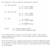
According to Argentine rules, we as ham radio operators have the following range in each band:
80mts: 3.5 to 4.0 MHz.
40mts: 7.0 to 7.3 MHz.
20mts: 14.0 to 14.35 MHz.
15mts: 21.0 to 21.5 MHz.
10mts: 28.0 to 28.7 MHz.
So, having the frequency chart of the FT75B extracted from the manual, I need the oscillators running at:
80mts: 8.627 to 9.127 MHz.
40mts: 12.127 to 12.427 MHz.
20mts: 8.87 to 9.22 MHz.
15mts: 15.87 to 16.22 MHz.
10mts: 11.43 to 12.22 MHz.
Thus taking round numbers, l have decided run them as:
80mts: 8.6 to 9.2 MHz.
40mts: 12.1 to 12.45 MHz.
20mts: 8.8 to 9.3 MHz.
15mts: 15.8 to 16.25 MHz.
10mts: 11.4 to 12.3 MHz.
It is then clear that 3 oscillators are needed:
For 80m and 20m from 8.6 to 9.3 MHz.
For 40m and 10m from 11.4 to 12.5 MHz.
For 15m alone, from 15.8 to 16.25 MHz.
The rounding is justified because no mechanical means home made can have high degree of stability and resolution for two or more decimal fraction values.
Attachments
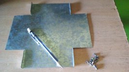
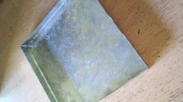
Now the VFO is +/- ok, then I shall make a box for it with a piece of thinker saved from the restoration of the roof many years ago. It has 12 x 12cm wide, and 5cm height. Sufficiently large to accomodate all parts, a PCB designed for it and in the front, some wheels saved from dismantled transistor radios. As I am old, l want my VFO looks as old as me.
Attachments
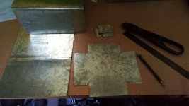
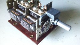
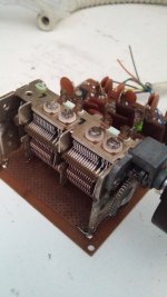
I owned two new gangs for the future oscillator for the rig. They have a native reduction 3:1 in the shaft giving 1.5 turns in the main shaft to move 180deg the variable capacitor rotor plates. It surely will add resolution for tuning the thin width SSB signals. Both are equal, have 3 section for FM (now for the 3 VFO's) and two for AM that are useless in my project. They will remain unused.
Attachments
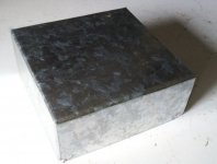
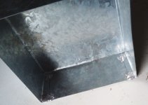
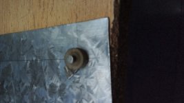
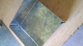
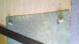
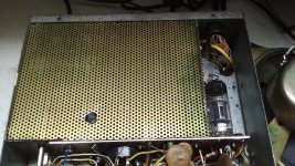
The original shield for the output stage was missing before I owned this rig. Thus I made a new one from holed thinker. The large hole brings access to the neutralizing trimmer.
Attachments
- Home
- General Interest
- Everything Else
- Restoration and modding of a vintage FT75B tranceiver.