
Thank you! For some reason my google search didn't see it...I had it saved and printed somewhere, but couldn't find it.
I had some vague thoughts from the past about this amp, but this is perfectly in line with my latest phono project and made up my mind for the mm section of my next preamp.
As I discarded 2 x 2700 $ 1986 Transbridge TBM4 amplifiers, I got left with some awesome supplies and boards full of very high quality switches and two INA110KP which fortunately are still in production if I ever need two more.I just hope the golden IC's are still working...I am going to replace thr whole balanced input stage of P-10 preamp with INA110KP left from the TBM4 amp and set its gain at 10x , just enough to get into a bunch of Signetics NE5534AN inverting stages doing the riaa eq.
I have 6 more INA102 left from tbm4 but their slew rate is really low so I only hope my 2 x ina110 are good cause they are damn expensive if I need to replace one after the job is done.
I bet there are better balanced input op amps today although not too cheap, but this one might allow me to remove the input capacitor into the next stage.
The bridge supply is done from two series lm317/337 so I'll be able to limit the input stage supply around +-5v taking in the account the maximum possible headroom needed so I'd have a cold low noise input chip doing the 10x gain.
Attachments
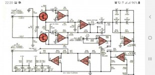
Here's the original Popular Electronics article for the P10: https://proaudiodesignforum.com/ima...eamplifier_Popular_Electronics_March_1981.pdf
The P100 schematic is here: https://www.proaudiodesignforum.com/forum/php/viewtopic.php?p=1470#p1470
You can find John Roberts at GroupDIY where he moderates.
I (and SSM previously) used the P10s RIAA EQ to provide analog EQ for my flat balanced-in/balanced-out MC and MM preamps. https://proaudiodesignforum.com/forum/php/viewtopic.php?t=753
Phono Transfer System: https://ka-electronics.com/shop/index.php?route=product/category&path=66
Last edited:
Cool stuff people.Thank you! I've read most of it back in 2014, but forgot the sources, developments.I knew it was a professional take on the subject anyway.
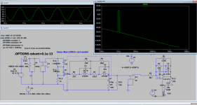
I was going to replicate Taylor's phono design with ne5534, but then this fights common mode noise and distortions more naturally. It's just the gain(10x) and of the input stage that will be significantly lower in my design to get the best noise and distortions out of INA110 which has the best signsl treatment at 10x gain and let ne5534 inverting stage and higher supply (+-20v) to take care of ne5534 inherent common mode distortions .
I was going to replicate Taylor's phono design with ne5534, but then this fights common mode noise and distortions more naturally. It's just the gain(10x) and of the input stage that will be significantly lower in my design to get the best noise and distortions out of INA110 which has the best signsl treatment at 10x gain and let ne5534 inverting stage and higher supply (+-20v) to take care of ne5534 inherent common mode distortions .
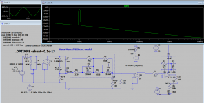
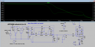
Avoided the differential input while attaching Attached Hans-MarcelVdg shure v15type3 model and although I have no ne5534 model in my library I abused LT115 one at highest possible output with +-20v supplies.Some clamping diodes need to be placed for higher inputs.
300mWatts is the max heat dissipation with 150mv input which is to be expected but also the minimum cause you need to keep the ic supplied at +-20v all the time unless you apply some rail bootstrap.I tried rail bootstrap with ne5534 following D Self schematics in noninverting topologies and I didn't like the sound.Maybe doing it with inverting topologies would work better although rail bootstrap was devised for unity gain noninverting topologies to overcome common mode distortions.Final stage bootstrap would help heat dissipation but make worse the input stage VCE variation...I'd heatsink the ne5534 hoping Iwon't affect its overall stability through distributed capacitance to all nodes as seen in the dimulation a cshunt directive above 1pF doesn't help the stability...
300mWatts is the max heat dissipation with 150mv input which is to be expected but also the minimum cause you need to keep the ic supplied at +-20v all the time unless you apply some rail bootstrap.I tried rail bootstrap with ne5534 following D Self schematics in noninverting topologies and I didn't like the sound.Maybe doing it with inverting topologies would work better although rail bootstrap was devised for unity gain noninverting topologies to overcome common mode distortions.Final stage bootstrap would help heat dissipation but make worse the input stage VCE variation...I'd heatsink the ne5534 hoping Iwon't affect its overall stability through distributed capacitance to all nodes as seen in the dimulation a cshunt directive above 1pF doesn't help the stability...
Attachments
Last edited:
Looking at the schematic I don't see any negative voltage connection to the FET sources. Am I missing something?
What fet sources? I'm gonna use INA110 wired for 10 x gain instead of the whole differential stage of P10.
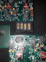
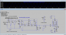
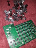
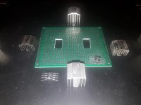
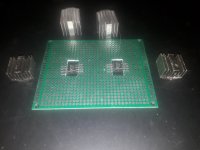
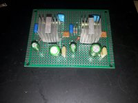
The solutions to +-20V(maybe max +-22v !?!) supplied ne5534 phono preamp attacked me today in great number.Well I need to rearange the sokets so that each IC should have its own heatsink which is not possible right now....
Attachments

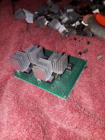
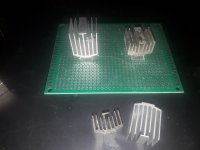
Today I made an evaluation for the required stability if heatsinks are added and strapped to ground... If I place one heatsink over the ne5534 I have 1...2pF capacitance from each pin to heatsink.If I add a second heatsink on the bottom side I get 3...5pF capacitance from heatsink to each pin so I might need to add further compensation even in 10x gain setting .I should call it WOW phono preamp to honour War of Worlds octopus space crafts 🙂
Attachments

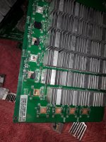
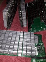
I'm changhing plans for the pcb work.The input INA110 will have its own pcb as well as the NE5534 chips.As NE5534 will go with the highest supplies ever seen in a phono preamp based on NE5534 with a minimum thermal dissipation expected to be around 160mW per dip case, the measures taken will be extreme to preserve the lowest noise and output impedance possible with this chip although the implied distributed capacitance to ground if I connect the cases to gtound might need some additional compensations.
I actually made a promiss that every single dip8 op amp chip I'll be using in the future will get similar treatment if possible.
I actually made a promiss that every single dip8 op amp chip I'll be using in the future will get similar treatment if possible.
Attachments
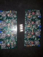
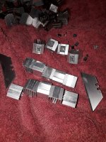
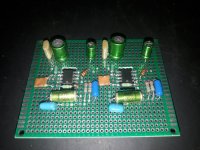
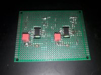
Made a little bit of progress with the inverting stage...I still need to add some power supply decoupling between +and - rails and probably a virtual ground generator too. The NE 5534AN Ic's are already anonymized through polishing as I prepared them for glueing to the heatsink, but I'll need to make a full functionality test before glueing.
I'll need
I think I forgot to tell that I'm actually cloning the inverting stage from Rotel RC 780/750 .
I only retained P10 principles of operation.
I'll need
I think I forgot to tell that I'm actually cloning the inverting stage from Rotel RC 780/750 .
I only retained P10 principles of operation.
Attachments

- Home
- Source & Line
- Analogue Source
- John Roberts P-100 complete schematic with bom