I'm working on an amp that uses an 8098 transistor,,, the schem I found for it shows a common 2n3904, so I ordered them... When the new parts came in, I started to replace them one at a time, but this one was 8098... Seems 2n3904 was used on earlier builds, but 8098 is rated C-B v 60v vs 40 for 3904,,,
and C-current max is .5v vs .2v,,,
Can anyone help with a sub or 8098 source? This is how the transistor is labeled...
AMPS
8098
ECB
TIA
and C-current max is .5v vs .2v,,,
Can anyone help with a sub or 8098 source? This is how the transistor is labeled...
AMPS
8098
ECB
TIA
On Semi MPS8098 was a rather high gain npn TO92 transistor, 60 v Vce. EBC pinout. More commonly stocked was the MPS8099 an 80 v similar transistor.
I haven't seen these in stock for a few years. On is still supportingTO92 EBC MPSA05 60v and MPSA06 80 v. When I needed ECB I found some BC639 80 v stocked at Newark (US farnell) in their house brand multicomp. A 60 v BC637 is on the datasheet but I never saw any in stock.
I haven't seen these in stock for a few years. On is still supportingTO92 EBC MPSA05 60v and MPSA06 80 v. When I needed ECB I found some BC639 80 v stocked at Newark (US farnell) in their house brand multicomp. A 60 v BC637 is on the datasheet but I never saw any in stock.
You haven't said which Q# you are replacing. 2n3904 is a jelly bean part, whereas On MPS8098 had minimum gain 75 @ 100 ma. On MPSA06 is 100. You probably don't need that much gain. The MPS8099 I installed in my AX6 had gain ~300 which I used to give my amp an input impedance of ~300 kohms instead of 100. I haven't been able to get On MPS8099 since they shut down Philippine fab.
MPS8098 has Ft 150 mhz, MPSA06 100 mhz. Both should be fast enough for audio.
You said your dead part say "AMP" instead of On, so who knows what the specs of your part are? I've had On even substitute a cheaper lower power package by issuing a new datasheet and changing the suffix code, so download the datasheet the day you purchase from the authorized distributor I my recommendation. Not a guarentee, Farnell sold me some Toshiba part # transistors with a link to a Toshiba datasheet, but the part logo showed it was made by some rotgut ****ese fab. NTE & Central Semi cover a lot of nifty part number parts with generic garbage by leaving out most of the specifications on their own datasheet.
Last edited:
All the info I posted was on the transistor I want to replace,,, the only schem I could find is in a 10 page manual with differently dated pages,,, The schematic is the newest page I have, which shows AMP 8098,,, which apparently was an upgrade for 2n3904 which was shown on the 79 dated schem I have,,, The earlier dated layout sheets in my manual dont include Q17, the 2n3409,,,
EB v, of 4v in MSPA06 vs 5v in 8098,,, and hfe of 100 in MSPA06 vs 100/300 in 8098 are my concerns... Other than the higher C-Ev of MPSA06 of 80v vs 60v... all the other data values are the same.... I chose MSPA06 from your post as it is readily available at Digi key....
I hope I answered your post, as I am a tube guy that is trying to rebuild this vintage SS amp!!!
What does "jelly bean part" mean??? !!
Thanks for the info and help...
Absolute max voltage Veb0 4 should be fine, you are never going to have the base of Q17 open.
A temperature sense transistor like Q17 on the left schematic should require only gain of 10. 100, 300 it doesn't need that much. This is a triple emitter follower output stage so the current to base of Q7 Q8 should only be 100 ma or less. The Q17 swings from a volt off either end of +-48 v rails, so no wonder a 40 v part like 2n3904 didn't last. I think an 80 v part like ON MPSA06 will be even tougher.
Note Q17 has to be thermally coupled to the output transistor heat sink. Don't use heat sink compound containing aluminum or silver (for PC CPU's). The generic titanium dioxide compound should be fine.
By jelly bean part I meana part everybody makes, everybody stocks, costs $.07, most found in local shops will be counterfeit. Allen is a serious pro organ company and has a very tight incoming inspection department as the organs they sold cost $20000 up in 1980. I upgraded power amp e-caps in a 1980 300 organ that went silent in 2017. There are still hundreds of electrolytic and tantalum caps in it soldiering on.
Last edited:
Again thanks for your time replying and explaining to my thread!!! My friend that works for a professional audio contractor gave me this amp... They would rather sell new gear than mess with something like this!!! My amp is probably from teh 80s, and getting info on it is been pretty hard, so I'm workin with what I got!
Not sure if you can see teh manual I posted, but on page 4 there is a parts layout page dated 1977, it still doesn't include Q17, which appears on the schem in 1979,,, There is a revisions box showing a bunch of parts that aren't on my board, so that's how I'm dating it later... I never saw any paperwork that included the 8098....
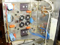
This transistor was clamped in a small metal tube that was bolted to the back wall of teh chassis,,, no thermal grease was on the transistor or in the tube,,, just between it and the wall....
The 8098 was mounted on the right wall, half way down in the pic where the white grease spot is,,
Thanks' again for the help!!!
John
Not sure if you can see teh manual I posted, but on page 4 there is a parts layout page dated 1977, it still doesn't include Q17, which appears on the schem in 1979,,, There is a revisions box showing a bunch of parts that aren't on my board, so that's how I'm dating it later... I never saw any paperwork that included the 8098....
This transistor was clamped in a small metal tube that was bolted to the back wall of teh chassis,,, no thermal grease was on the transistor or in the tube,,, just between it and the wall....
The 8098 was mounted on the right wall, half way down in the pic where the white grease spot is,,
Thanks' again for the help!!!
John
Attachments
Last edited:
That back wall of the chassis where the TO3 transistors are (outputs) is the somewhat inadequate heat flange. The grease spot is thermal grease, which you should install between the aluminum tube holding Q17 and the chassis wall. I use dowcorning 340 heat sink compound, although there have been others in smaller packages that are cheaper. Digikey will have something in a small quantity like 1 or 2 oz.
That looks a lot like the 1980 Allen S100 amps I had to work on. They are 100 w 4 ohms amp, went silent in a service one Sunday in 2017. Replacing the big blue caps got it to 40 watts. that bipolar blue cap with the crimps on both ends, when I changed that the power went back to 100 watts.
That looks a lot like the 1980 Allen S100 amps I had to work on. They are 100 w 4 ohms amp, went silent in a service one Sunday in 2017. Replacing the big blue caps got it to 40 watts. that bipolar blue cap with the crimps on both ends, when I changed that the power went back to 100 watts.
My forum buddy sent me a small tube of thermal grease... He has been following this thread, and told me to confirm it will work OK with you when it gets here,,,
There seems to have been a big short thru this amp when I got it,,, most of the transistors I replaced were blown,,, The replaced squared off blue cap in teh pic, next to the finned heat sinks had a 68r cap under it, teh resistor blew apart, leaving the two leads under the melted cap... I replaced the brown disc cap next to it yesterday, as it was black from the burning, but it read .01 like teh schem, so thats what I used...
This amp is rated 150W/4R,,, 100W/8R... I'm not sure if its each channel or bridged together...
Sounds like your amp wasn't as bad as this one,,, I hope I can get this one sorted!!
I started a thread here when I got the amp, looking for a schem, but no joy,,, and there is the same one running on Audiokarma, with only interest from a couple guys I know from the tube forum, so your help has been great...
Thanks again for the help and interest!!
Proper heat sink grease for this is white, not silver.
The blue squared off cap is a polyprophylene or mylar film cap. Don't blow often unless a big meltdown as you amp had. Blown heat sense transistor is a symptom of all the output transistors, drivers, predrivers taken out. Real organ S100 amp has a heat sink about 8"x8"x11" attached by thermal grease to that flange the TO3 output transistors are on. No fan. 100 watts (4 ohms) all day if you hold the pedal down that long.
The blue electrolytic caps just dry out from old age. Should be a couple of big ones outside the chassis, 14000 uf 63 v in case of the two I repaired. High ESR, and capacitance 16000 uf causing the 2 watt performance.
Didn't realize it was an Allen organ amp with a guitar/bass front end pcb until I looked at the schematic. I repair old organs for churches, no sense spending $30000 for a new one or moving to a trashy import keyboard with rubber key contacts if all is wrong is dried up 28 year old e-caps. The allens have gold plate key contacts.
OK,, so if the grease I get is white, its OK? I'm glad you replied to this thread!!! I'm a retired electrician,, a buddy that worked for me gave a a bunch of tubes and said go build something about 10 or so years ago,,, so I learned some tube stuff,,, rebuilt I a couple amps,, and then started building from scratch, mostly from parts I got at hamfests!!! Been building guitar amps lately....
I have a couple big heatsinks, think I should look into using them on this?
I have a couple big heatsinks, think I should look into using them on this?
A flat plate with no fins is not an adequate heatsink for a +-41 v rails amp. RMI bought the boards from Allen organ but not the heat management design, IMHO. Could be why the transistor meltdown (other possible cause is short in the speaker coil or speaker wiring). The Allen 300 organ S100 amps have the 2 T03 transistors (each) mounted externally on the heat sink above the chassis. In the middle of the 8"x8"x11" ball of fins.
I've increased heatsink on 2 other amps prone to burn output transistors, dynaco ST120 and a PV-4c. Both worked fine afterwards. I used 2 Pentium 2 computer CPU heatsinks on the ST120. Putting O.T.s 6" away from the driver transistors can cause oscillation, so be careful. Inductive stoppers on the base wires of O.T. may be necessary, like one turn around a little ferrite toroid. Or a ferrite bead on the base line. If you move the sense transistor out near external output transistors, inductors back in the wires back to the predriver emitters may be necessary. I did that to the ST120, but it had the heat sense feedback a different place, emitter of the VAS transistor. If you can thermally couple the new heatsink to the Output transistors in their present location, that eliminates the oscilaltion risk.
I've increased heatsink on 2 other amps prone to burn output transistors, dynaco ST120 and a PV-4c. Both worked fine afterwards. I used 2 Pentium 2 computer CPU heatsinks on the ST120. Putting O.T.s 6" away from the driver transistors can cause oscillation, so be careful. Inductive stoppers on the base wires of O.T. may be necessary, like one turn around a little ferrite toroid. Or a ferrite bead on the base line. If you move the sense transistor out near external output transistors, inductors back in the wires back to the predriver emitters may be necessary. I did that to the ST120, but it had the heat sense feedback a different place, emitter of the VAS transistor. If you can thermally couple the new heatsink to the Output transistors in their present location, that eliminates the oscilaltion risk.
OK, Thanks,,,
"If you can thermally couple the new heatsink to the Output transistors in their present location, that eliminates the oscilaltion risk." This would be my plan, even if each sink had to be cut so a quarter of it would serve each transistor...
The ones I have had four 3055 transistors on each of them and one had a big diode to reverse teh output for teh opposite rail... They are about 8" long and are made of thick aluminum with good size fins the length of them... If I can mount them over the holes in the panel of the amp, and use one heat sink for each pair of OTs,,, it would probably cool it down some...
I grabbed em at a hamfest for a buck, hoping a transistor or two would be usable,, and all 8 work!!!
I think the heat sinks are at my buddy's place, as I wanted the 3055s,,, I'll have to ask him to dig em out,,,,
Think leaving the OTs where they are and adding fans would do any good? It would probably eliminate the oscillation threat,,, and be a lot easier to do,,,
This amp came from a school music dept,,, good chance a kid shorted speaker wires, for this much damage... It looks like it became a welder till the 4A fuse blew!!!
But I gotta see if I can get it working first!!!!
Heat transfer by convection occurs at the edge. Flat plates don't have much edge. The more edge, the more heat transfer. In your picture I see the output transistors mounted on a flat plate.
I could suggest you could add some TO3 heatsink with fingers to the flat plate, instead of those obsolete transistor sockets your chassis uses. digikey doesn't have a search heatsinks by package type, so the first TO3 heatsink of the 563 wakefield parts that comes up is this one https://www.digikey.com/en/products/detail/wakefield-vette/680-125A/340347 which at $16 each costs about 12 times what I paid for the ones I installed in the PV-4c. I tapped the regular heat sink for #6-32 screw, installed some heat grease, and screwed them down. My first PV-4c had 2 sets of initials of techs that replaced the output transistor set before me.
Heat transfer by convection is proportional to the air speed squared or cubed. So a fan might help. But I don't personally have much faith in the efficiency of a flat plate. Djoffe tried flat plate at first in his ST120 upgrade kit, then when the atikita website went online he was selling a finned heat sink that cost about $35 as an accessory to the base kit. I've been running my ST120 on two TO3 finned heatsinks per side added to the OEM aluminum angle mount, with a PCAT ATX supply fan flow run at 9 vdc instead of 12. Reliability was good but my O.T.'s run at 69 v single supply versus the RMI360 82 v supply (+-41).
I hear what you're saying and am one for improving a design,,, but I also believe in getting an amp running before adding changes,,, I sent the Digi order in this morning so now we wait for parts... I really not convinced I found all the problem with this one yet tho...
Only positive news is I powered up the preamp/control section and am able to get signal thru it, so now its up to the power section!! And the power supply works also...
Only positive news is I powered up the preamp/control section and am able to get signal thru it, so now its up to the power section!! And the power supply works also...


- Home
- Amplifiers
- Solid State
- 8098 transistor or sub...