help.
I want to make a HV PS with bridge rectifier tubes because a secondary Single Coil transformer that doesn't use CT. Can it? because I've searched on google, it's not there.
I want to make a HV PS with bridge rectifier tubes because a secondary Single Coil transformer that doesn't use CT. Can it? because I've searched on google, it's not there.
A bridge rectifier has 4 rectifiers. Are you saying you want to use it with 4 tube rectifiers??
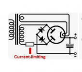
What people normally do in such a situation is use two solid state diodes and one dual tube rectifier.
Must be a million on Google. Attached the very first hit with 'tube rectifier'.
https://www.diyaudio.com/community/threads/bridge-rectifier-with-fullwave-tube.266468/
Jan
What people normally do in such a situation is use two solid state diodes and one dual tube rectifier.
Must be a million on Google. Attached the very first hit with 'tube rectifier'.
https://www.diyaudio.com/community/threads/bridge-rectifier-with-fullwave-tube.266468/
Jan
Attachments
Last edited:
Thank so much Jan.A bridge rectifier has 4 rectifiers. Are you saying you want to use it with 4 tube rectifiers??
What people normally do in such a situation is use two solid state diodes and one dual tube rectifier.
Must be a million on Google. Attached the very first hit with 'tube rectifier'.
https://www.diyaudio.com/community/threads/bridge-rectifier-with-fullwave-tube.266468/
Jan
I am not sure what are need HW rectifier tube x4 , because i assume that need four tube like solid diode. But this link will be helpful.
Regards
Ed
Have a loo here, the bridge with 4 dampers is used in almost all his designs. If you look in older Posts he shows the actual schematics. Hint: one has to pay attention to the voltage limits between heater and cathode.
http://vinylsavor.blogspot.com
http://vinylsavor.blogspot.com

Thank you .Have a loo here, the bridge with 4 dampers is used in almost all his designs. If you look in older Posts he shows the actual schematics. Hint: one has to pay attention to the voltage limits between heater and cathode.
http://vinylsavor.blogspot.com
That are used Damper tube of vinylsavor, and i have 4 X 3B28 half wave rectifier tube, and i think that be used for bridge. And i look impossible to do that.
You can use the 3B28 instead of the dampers. You will need several separated and well isolated secondaries to power the 3B28s. What is impossible in doing that?
I'm sorry, I don't understand and confused, with the schematic with Half wave Rectifier with direct heater. because confused to get a CT (-).You can use the 3B28 instead of the dampers. You will need several separated and well isolated secondaries to power the 3B28s. What is impossible in doing that
Please can you provide a picture of the schematic example.
Thank you
If your xfrmr has no CT you need a full bridge with 4 diodes. You can use a dual tube rect and two solid state diodes. I showed the schematic.
Jan
Jan
I have look for your schematic, it clear with diodes.
I told about if i want used 4x HW rectifiers like diodes bridge rectifier.
I told about if i want used 4x HW rectifiers like diodes bridge rectifier.
?? Same schematic, replace dual tube with two solidstate diodes. Now you need 4 solid state diodes, or one bridge. There are million on Google.
With your tubes it goes like this.Thank you .
That are used Damper tube of vinylsavor, and i have 4 X 3B28 half wave rectifier tube, and i think that be used for bridge. And i look impossible to do that.
Mona
Attachments
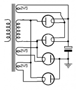
Yes, this is what I've been looking for all along.With your tubes it goes like this.
Mona
thank you very much.
i love it
i will go it with my 833 tube.
thank you
regards
ed
- Home
- Amplifiers
- Tubes / Valves
- help. schematic for PS HV Bridge using Half wave Rectifier tube ×4.