hello,
i want to use this yamaha cdx1060 as dac, and connect them to a streamer.
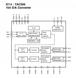
the dac chip is YM506 and it is 1bit as datasheet said.
i tried to connect this ym506 with my streamer via i2s pins.
but it didn't work, only noise sound appear.
(i guess because of that 1bit dac chip can not accept directly common 16bit pcm)
how to connect them properly? pls help.
thanks.
Peter
i want to use this yamaha cdx1060 as dac, and connect them to a streamer.
the dac chip is YM506 and it is 1bit as datasheet said.
i tried to connect this ym506 with my streamer via i2s pins.
but it didn't work, only noise sound appear.
(i guess because of that 1bit dac chip can not accept directly common 16bit pcm)
how to connect them properly? pls help.
thanks.
Peter
Attachments
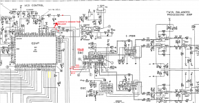
There could simply be a problem with the master clock. In the CD player, the YAC506 provides a master clock to the chip that drives it, rather than the other way around.
If your I2S interface provides a master clock, like most of them do, you could try applying it to pin 7 of the YAC506.
Unfortunately the YAC506 expects 384 times the sample rate as clock frequency, while most USB to I2S interface boards only supply powers of two times the sample rate, for example 22.5792 MHz instead of 16.9344 MHz. I guess you just have to try and see if that works.
Another approach would be to try and find a YAC506 datasheet and search for a description of the input interface and the clock frequency requirements.
Last edited:
Another thing: what are the voltage levels at the streamer I2S output? The YAC506 probably expects 5 V CMOS levels. If it happens to be designed with TTL-compatible inputs, 2.5 V and 3.3 V CMOS levels should also work.
hello MarcelvdG,
voltage at streamer is : 1.2v(BCK) 1.4v(LRCK) 2.5mv(DATA)
i couldn't found any YAC506 datasheet on google.
the only data of this chip found on yamaha service manual, shown below.
i will try to connect streamer MCLK to YAC506 pin7(Xin).
(or should it be pin6 which is Xout?)
voltage at streamer is : 1.2v(BCK) 1.4v(LRCK) 2.5mv(DATA)
i couldn't found any YAC506 datasheet on google.
the only data of this chip found on yamaha service manual, shown below.
i will try to connect streamer MCLK to YAC506 pin7(Xin).
(or should it be pin6 which is Xout?)
Attachments
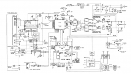
Just to be sure: did you only connect the streamer or also disconnect the YM7402 from the DAC chip? The connections to the YM7402 have to be cut.
I guess those are average voltages measured with a multimeter, rather than high levels measured with an oscilloscope, is that correct?
That's a pity, but at least the picture confirms that the conversion from multibit to single bit is done inside this chip.
Pin 7, otherwise you have two outputs fighting each other. Disconnect the circuit that normally drives pin 7.
If this doesn't work, the next thing you could try is inserting some sort of level shifter, for example a 74AHCT125.
hello MarcelvdG,
voltage at streamer is : 1.2v(BCK) 1.4v(LRCK) 2.5mv(DATA)
I guess those are average voltages measured with a multimeter, rather than high levels measured with an oscilloscope, is that correct?
i couldn't found any YAC506 datasheet on google.
the only data of this chip found on yamaha service manual, shown below.
That's a pity, but at least the picture confirms that the conversion from multibit to single bit is done inside this chip.
i will try to connect streamer MCLK to YAC506 pin7(Xin).
(or should it be pin6 which is Xout?)
Pin 7, otherwise you have two outputs fighting each other. Disconnect the circuit that normally drives pin 7.
If this doesn't work, the next thing you could try is inserting some sort of level shifter, for example a 74AHCT125.
Last edited:
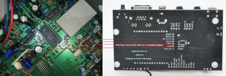
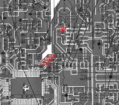
i attached pictures where i cut the line.tJust to be sure: did you only connect the streamer or also disconnect the YM7402 from the DAC chip? The connections to the YM7402 have to be cut.
correct haha...I guess those are average voltages measured with a multimeter, rather than high levels measured with an oscilloscope, is that correct?
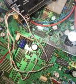
i have tried to connect the pins as picture below, but no luck, still no sound coming out.If this doesn't work, the next thing you could try is inserting some sort of level shifter, for example a 74AHCT125.
so i guess have to try inserting 74AHCT125 to this dac? how to do that?
thanks.
Attachments

In the OP's shoes, I would not automatically assume that a Japanese device from the relatively early days of digital audio would conform to a European digital audio interface. Not everything accepts or transmits I2S.
Build this circuit, mount it close to the YAC506 and run each of the four signals through one of the buffers. The circuit is to be supplied from the same supply as the YAC506.

The 74AHCT125 contains four identical buffers, so it doesn't matter which buffer is used for which signal, just connect them in whatever way makes the wiring least messy.
Depending on the brand and the package, there may be some letters before and after the type number. For example SN74AHCT125N for one from Texas Instruments in an old-fashioned DIL package.
Make sure not to use 74AHC125 instead of 74AHCT125, as that won't work.
I'm not sure what to do with the 1 kohm resistors. I guess they are there for a reason, so I think they have to be in the lines from the 74AHCT125 to the YAC506.
Good point, and the odd clock frequency may well be a problem. I'm not at all sure that the circuit of the previous post is going to work, but it might. If it doesn't, I'm out of ideas. (Well, you could use another converter to single bit instead of the YAC506 and only retain the flip-flops and analogue stuff, but you might as well make everything from scratch then.)In the OP's shoes, I would not automatically assume that a Japanese device from the relatively early days of digital audio would conform to a European digital audio interface. Not everything accepts or transmits I2S.
Edit: if it works at low volumes (digital volume below half scale) and distorts like hell at higher volumes, it is probably a misaligned MSB. That could be solved with an extra flip-flop (one part of a 74AHCT74 for example), or maybe with a firmware setting of the streamer.
Last edited:
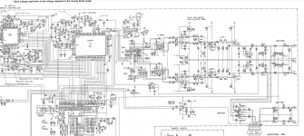
I made a stupid mistake. The (preferably level shifted) master clock has to be connected to pin 1 of IC15 (74HCU04), the connection from IC15 to the YAC506 has to be restored to what it was in the CD player. I overlooked that the 74HC00's also need the proper clock.
Last edited:
Apologies for the many posts in a row. In order to minimize crosstalk from data to master clock, which could degrade the noise floor, this is a better approach:
Pass the data, bit clock and word clock through the 74AHCT125, like in post #8
Ground the remaining 74AHCT125 input and leave the corresponding output open
Restore the connection from IC15 to the YAC506, as it used to be
Remove the crystal connected to IC15, leave the other components around IC15 in place
Capacitively couple the master clock into IC15 pin 1 using a 1 nF coupling capacitor
IC15 will now act as the level translator for the master clock. As it is separate from the 74AHCT125 used for the other signals, there is less risk of crosstalk to the master clock.
hello MarcellvdG many thanks for the help.Apologies for the many posts in a row. In order to minimize crosstalk from data to master clock, which could degrade the noise floor, this is a better approach:
Pass the data, bit clock and word clock through the 74AHCT125, like in post #8
Ground the remaining 74AHCT125 input and leave the corresponding output open
Restore the connection from IC15 to the YAC506, as it used to be
Remove the crystal connected to IC15, leave the other components around IC15 in place
Capacitively couple the master clock into IC15 pin 1 using a 1 nF coupling capacitor
IC15 will now act as the level translator for the master clock. As it is separate from the 74AHCT125 used for the other signals, there is less risk of crosstalk to the master clock.
okay i will try this.
i will update the result.

For anyone who wants to know: according to https://manuals.plus/arylic/up2-stream-pro-v3-wi-fi-and-bluetooth-audio-receiver-manual the master clock frequency of the streamer board is 11.288 MHz (I assume they mean 11.2896 MHz as that is 256 times 44.1 kHz), it works in master mode, the interface format is I2S and the sample rate and word length are 44.1 kHz and 16 bit.
- Home
- Source & Line
- Digital Source
- Yamaha CDX-1060 with 1-BIT DAC