G'day Guys,
I've been brewing up a PSU board to use for a Rod Elliot P3A that I have in the works.
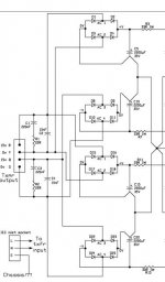
The idea here is to have something simple, robust and modular such that it can be used for other projects in the future.
I would be ordering with 2oz copper.
I've put in plenty of extra pads to account for parts substitutions eg; different sized film caps, resistors, screw terminals instead of spade connectors etc
By my maths I need 3 +/- connections ( 1 for each amp board and 1 for speaker protection) and 6 grounds; 2 for amp boards, 2 for speaker ground return, 1 for speaker protection and 1 for the chassis earth.


Any criticisms or feedback?
Is anything I have done here simply daft?
Am I good to go?
Many Thanks
Sadface
I've been brewing up a PSU board to use for a Rod Elliot P3A that I have in the works.
The idea here is to have something simple, robust and modular such that it can be used for other projects in the future.
I would be ordering with 2oz copper.
I've put in plenty of extra pads to account for parts substitutions eg; different sized film caps, resistors, screw terminals instead of spade connectors etc
By my maths I need 3 +/- connections ( 1 for each amp board and 1 for speaker protection) and 6 grounds; 2 for amp boards, 2 for speaker ground return, 1 for speaker protection and 1 for the chassis earth.
Any criticisms or feedback?
Is anything I have done here simply daft?
Am I good to go?
Many Thanks
Sadface

Hi, I had started a thread similar to this.
Pls have a look at, to get some suggestions on routing the tracks on the PCB.
Its located at : https://www.diyaudio.com/community/threads/crc-psu-pcb-for-class-a-ab-amps.389854/#post-7121364
Pls have a look at, to get some suggestions on routing the tracks on the PCB.
Its located at : https://www.diyaudio.com/community/threads/crc-psu-pcb-for-class-a-ab-amps.389854/#post-7121364
1. Use a single bridge not two. It is much more safe for the amplifier and in special for speakers in case of a failure in power supply.
2. You do not need 1ohm 3W resistor serie with a 100nF capacitor. Use 0.25W resistor there.
3. Put R-C shubers across every diode bridge (use only one bridge). The values for these snubers components will be different everytime because depends of the used transformer and diodes parameters.
2. You do not need 1ohm 3W resistor serie with a 100nF capacitor. Use 0.25W resistor there.
3. Put R-C shubers across every diode bridge (use only one bridge). The values for these snubers components will be different everytime because depends of the used transformer and diodes parameters.
The idea being that the smaller cap will be more effective at higher frequencies.Why 100u in parallel with 10mF?
I've seen it elsewhere on this forum that this works best when the smaller cap is 1/100 the size of the larger one ( I think it was Elvee that stated this in the denoiser thread)
This is also why I chose 1uF for the film cap.
I've not encountered point 1 before, only the opposite, that dual bridges is a better solution as one is splitting the current across 2 bridges.1. Use a single bridge not two. It is much more safe for the amplifier and in special for speakers in case of a failure in power supply.
My understanding was that this is also a lower noise solution as the ground is effectively isolated from the transformer noise by the bridges.
Am I erroneous here?
The bridges will be bolted to the chassis for cooling.Have you considered cooling the rectifiers?
The idea being that the smaller cap will be more effective at higher frequencies.
I've seen it elsewhere on this forum that this works best when the smaller cap is 1/100 the size of the larger one ( I think it was Elvee that stated this in the denoiser thread)
This is also why I chose 1uF for the film cap.
smaller caps are best used right at the load side of the psu...this has been discussed to death before many many years ago....i guess myths are hard to die....search for poster Eva for more info...
G'day Guys,
I've been brewing up a PSU board to use for a Rod Elliot P3A that I have in the works.
The idea here is to have something simple, robust and modular such that it can be used for other projects in the future.
I would be ordering with 2oz copper.
I've put in plenty of extra pads to account for parts substitutions eg; different sized film caps, resistors, screw terminals instead of spade connectors etc
By my maths I need 3 +/- connections ( 1 for each amp board and 1 for speaker protection) and 6 grounds; 2 for amp boards, 2 for speaker ground return, 1 for speaker protection and 1 for the chassis earth.
View attachment 1097654
View attachment 1097655
View attachment 1097653
Any criticisms or feedback?
Is anything I have done here simply daft?
Am I good to go?
Many Thanks
Sadface
Neson Pass invented this psu scheme, simply to take our the secondary of traffos out, that is no galvanic contact....it made a lot sense to me so i have never looked back at center tapped psu's...
traffos with bifillar secondaries, started in the 1980's by Jim Bongiorno's GAS Ampzilla amp..
The idea being that the smaller cap will be more effective at higher frequencies.
If you're concerned about eliminating higher frequencies consider adding some series R or L between C1 and C3 (likewise on opposite polarity).
Point taken, does this apply to the film cap at the output or is this one still useful?smaller caps are best used right at the load side of the psu...this has been discussed to death before many many years ago....i guess myths are hard to die....search for poster Eva for more info...
since rectifiers are now dirt cheap, consider using 50A bridge when 10A is called for...
I haven't seen any 50A bridges in this footprint?
I've got a bunch of 25A types which is what I was planning to use.
The film cap is even worse. Try to simulate parallel capacitance with some real world elements added like ESR and ESL and the inductance and resistance of the PCB added to see the effect yourself. You will see huge peaks in the impedance curve due to resonance. CRC is almost always safe, CLC depends on the Q of the components.Point taken, does this apply to the film cap at the output or is this one still useful?
How about the snubber on the output?The film cap is even worse. Try to simulate parallel capacitance with some real world elements added like ESR and ESL and the inductance and resistance of the PCB added to see the effect yourself. You will see huge peaks in the impedance curve due to resonance. CRC is almost always safe, CLC depends on the Q of the components.
Undesirable also?
The use of two rectifier bridges is an audiophile fad and does not bring any practical benefit except heat dissipation.
Instead, it only brings shortcomings, among which the interruption of one of the bridges or a secondary in the transformer will lead to a voltage drop on one of the power supply branches and implicitly DC will appear at the speaker terminals.
In the case of a single bridge, the interruption of a secondary in the transformer will lead to the appearance of a large ripple on both supply lines and no DC will appear on the output.
In the case of 2 bridges, if the secondaries have slightly different voltages, the same will be the voltages after rectification and filtering. In the case of single bridges, the voltages will be identical, but only the voltage ripple will increase.
Of those who are fans of the wrong two-bridge rectifier, how many of them came to the conclusion that it is better just by simple analysis, and how many of them came to this conclusion after reading audiophile stories?
The question is how many of them still believe in unicorns.
No, snubbers are great. A snubber may even remedy an otherwise resonant network to some extend. However, to be most effective, the snubber should be optimized.How about the snubber on the output?
Undesirable also?
BTW: I forgot to mention that 2oz copper does not improve anything, quite the contrary. If you have higher resistance in the PSU, naturally CRC filters form an the Q of the whole filter gets lower, reducing any resonance that might appear. Voltage drop is less of a concern unless the current is very high. So by using 1oz copper you both save money and also improve the PSU.
Thanks for the feedback guys,
Here is my improved version.


I've chopped off the extra capacitors which saved a bit of space and complexity in the pours.
I will take the 1oz copper option and save myself the money.
I've decided to stick with the dual bridge.
Here is my improved version.
I've chopped off the extra capacitors which saved a bit of space and complexity in the pours.
I will take the 1oz copper option and save myself the money.
I've decided to stick with the dual bridge.
Point taken, does this apply to the film cap at the output or is this one still useful?
I haven't seen any 50A bridges in this footprint?
I've got a bunch of 25A types which is what I was planning to use.
film caps as rails bypass is best used at the amplifier boards themselves...
look at online sellers and you will find 50A flatpacks same footprints as a 25A on
You lose more volts (hence power, hence heat) through the extra diode drops, also.The use of two rectifier bridges is an audiophile fad and does not bring any practical benefit except heat dissipation.
Instead, it only brings shortcomings, among which the interruption of one of the bridges or a secondary in the transformer will lead to a voltage drop on one of the power supply branches and implicitly DC will appear at the speaker terminals.
In the case of a single bridge, the interruption of a secondary in the transformer will lead to the appearance of a large ripple on both supply lines and no DC will appear on the output.
In the case of 2 bridges, if the secondaries have slightly different voltages, the same will be the voltages after rectification and filtering. In the case of single bridges, the voltages will be identical, but only the voltage ripple will increase.
Of those who are fans of the wrong two-bridge rectifier, how many of them came to the conclusion that it is better just by simple analysis, and how many of them came to this conclusion after reading audiophile stories?
The question is how many of them still believe in unicorns.
I've decided to stick with the dual bridge.
sesebe wont like this, but i use four bridges to make L/R supplies.
Attachments
- Home
- Amplifiers
- Power Supplies
- Please critique my PSU