Hello! I have made a pcb design for a 300B amp(single channel), I have a 5V for the heaters separate because of the AC that is going to it. I am asking for any suggestion that might improve this layout. Thanks to all the people that responded to my previous post! (All the dots are just a reminder where everything connects)


6SN7 heater is floating, may cause hum.
Please read this thread:
https://www.diyaudio.com/community/threads/hum-problem-in-300b-set.371655/
Please read this thread:
https://www.diyaudio.com/community/threads/hum-problem-in-300b-set.371655/
I will definitely have a look at that when I build mine, what do you think about component placement? Would you make some changes?6SN7 heater is floating, may cause hum.
Please read this thread:
https://www.diyaudio.com/community/threads/hum-problem-in-300b-set.371655/
The footprints for the chokes L1 and L2 are way way too little.
Check out the physical dimensions of this choke:
https://www.tubesandmore.com/products/choke-one-electron-audio-prc-2-shunt-feed-se-output
I think you should have all the components' part number and manufacturers' footprints before
you layout your board.
Check out the physical dimensions of this choke:
https://www.tubesandmore.com/products/choke-one-electron-audio-prc-2-shunt-feed-se-output
I think you should have all the components' part number and manufacturers' footprints before
you layout your board.
I have made all the footprints myself based on the real components that I have, the chokes are custom made and have wires coming off of them so I just need to connect them at the points that are on the board. Do you think I should do it differently?The footprints for the chokes L1 and L2 are way way too little.
Check out the physical dimensions of this choke:
https://www.tubesandmore.com/products/choke-one-electron-audio-prc-2-shunt-feed-se-output
I think you should have all the components' part number and manufacturers' footprints before
you layout your board.
Small signal tubes' ground return seems to be mixing with the power tube's.
http://www.geofex.com/article_folders/stargnd/stargnd.htm
There are many wires flying off your board, do you really want to do it that way ?
http://www.geofex.com/article_folders/stargnd/stargnd.htm
There are many wires flying off your board, do you really want to do it that way ?
Grounds will all be seperate, the power tubes separately, input stage etc.. I'm gonna have local ground loops that go to one star ground? I have read that it is done like that? On my board there is writing 400V 1 5U4GB and that will not be on the board, it's just a reminder to connect the PT which will be under the rectifier tubes so the AC circit is as short as possibleSmall signal tubes' ground return seems to be mixing with the power tube's.
http://www.geofex.com/article_folders/stargnd/stargnd.htm
There are many wires flying off your board, do you really want to do it that way ?
What size are the solder pads for the filter caps and power resistor? they look small on the layout pic. I've done a few board designs & found .150" to be good diameter for large components. Through hole diameter should be easy to measure since you have the components.
Also important is trace thickness, can't tell by your diagram. Make sure the higher current traces are adequate. I use this online calculator:
https://www.digikey.com/en/resources/conversion-calculators/conversion-calculator-pcb-trace-width
The below jpeg is one of my later designs. B+, gnd, and heater traces are as wide as I had room for (.125"-.150")
Attachments
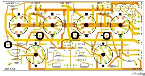
Thank you, I didn't make any traces yet just wanted to make sure everything is placed right. Do you have an Idea of how to position 4 chokes around the PT? Still not sure about that :/What size are the solder pads for the filter caps and power resistor? they look small on the layout pic. I've done a few board designs & found .150" to be good diameter for large components. Through hole diameter should be easy to measure since you have the components.
Also important is trace thickness, can't tell by your diagram. Make sure the higher current traces are adequate. I use this online calculator:
https://www.digikey.com/en/resources/conversion-calculators/conversion-calculator-pcb-trace-width
The below jpeg is one of my later designs. B+, gnd, and heater traces are as wide as I had room for (.125"-.150")
??- I only see 2 chokes...
I try to keep xfrmrs & chokes far away from PCB's & especially signal lines as possible to minimize noise from flux lines (not the flux capacitor ;<))
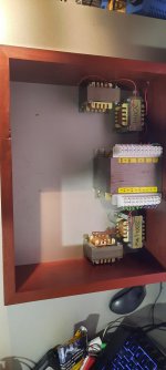
Helps also to keep adjacent cores @ 90 degree angles. For example mount the PT in the middle and clock the core @ 12 & 6. Then mount chokes each side clocked 3 & 9.
I try to keep xfrmrs & chokes far away from PCB's & especially signal lines as possible to minimize noise from flux lines (not the flux capacitor ;<))
Helps also to keep adjacent cores @ 90 degree angles. For example mount the PT in the middle and clock the core @ 12 & 6. Then mount chokes each side clocked 3 & 9.
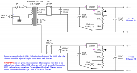
Are you fixed on that particular circuit? There are others on that forum and this one worthwhile looking at. I started off with a eBay version similar to this one but without the directly connect driver. Although happy with the sound I modified it similar to the suncalc design and Mwhouston build of the 300b set project also on diyaudioprojects. The one I built was a 3 stage variation on p. 33 of the thread. Worth checking the thread out at least.
I'm making a stereo amp so I need double everything except PT and I know about the 90° angle between them but there always seems to be two of them being in line with one another, should I build some kind of protection for the boards? Like incase them or something? Also Is it a good idea to put the PT in the case of the amp???- I only see 2 chokes...
I try to keep xfrmrs & chokes far away from PCB's & especially signal lines as possible to minimize noise from flux lines (not the flux capacitor ;<))
Helps also to keep adjacent cores @ 90 degree angles. For example mount the PT in the middle and clock the core @ 12 & 6. Then mount chokes each side clocked 3 & 9.
Nice! Yeah I wanna do this one, got the components and everything just need to get this pcb and I'm all set. Thanks for the reply!Are you fixed on that particular circuit? There are others on that forum and this one worthwhile looking at. I started off with a eBay version similar to this one but without the directly connect driver. Although happy with the sound I modified it similar to the suncalc design and Mwhouston build of the 300b set project also on diyaudioprojects. The one I built was a 3 stage variation on p. 33 of the thread. Worth checking the thread out at least.
No worries,I'm making a stereo amp so I need double everything except PT and I know about the 90° angle between them but there always seems to be two of them being in line with one another, should I build some kind of protection for the boards? Like incase them or something? Also Is it a good idea to put the PT in the case of the amp?
Just use a chassis style layout- Iron on top and pcb's inside of nonferrous metal... like aluminum or stainless steel. Hammond makes reasonably priced aluminum chassis style enclosures, wood side panels even as option-
https://www.hawkusa.com/sites/hawk-...facture_group/HAMND/Series 1444/spec/1444.pdf
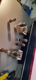
I have made my wooden chassis I just need to decide on plates. Wouldn't it be better if aluimum was on top and bottom? What do you think about these layouts?(the PT would be then on the inside and the tubes would be on top) No matter how I put the other choke is not going to be at the right angle with something, and my pcbs need to go under them or on the sides. What do you think is best? Or if you have another idea of doing this? Thanks for replying!No worries,
Just use a chassis style layout- Iron on top and pcb's inside of nonferrous metal... like aluminum or stainless steel. Hammond makes reasonably priced aluminum chassis style enclosures, wood side panels even as option-
https://www.hawkusa.com/sites/hawk-dev.ent.c-g.io/files/manufacture_group/HAMND/Series 1444/spec/1444.pdf
Attachments

I've been designing and building 300B amplifiers since the early/mid 1990s and have not achieved a satisfactory result with AC heating on the 300B filaments. (Hum) I recommend heating with DC, and the best option I have found are Rod Coleman's dht heater boards - I've used dozens of them.
https://www.lyrima.co.uk/dhtreg/dhtRegIntro.html
They are very reasonably priced, I recommend them. No affiliation with Rod, just experience based.
https://www.lyrima.co.uk/dhtreg/dhtRegIntro.html
They are very reasonably priced, I recommend them. No affiliation with Rod, just experience based.

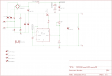
Hey, thanks for the reply! It is not going to be direct AC, I am running 6,3V from the PT to the rectifier circuit I made, I'll put a picture. The 5V is for the 5U4GB Tubes.I've been designing and building 300B amplifiers since the early/mid 1990s and have not achieved a satisfactory result with AC heating on the 300B filaments. (Hum) I recommend heating with DC, and the best option I have found are Rod Coleman's dht heater boards - I've used dozens of them.
https://www.lyrima.co.uk/dhtreg/dhtRegIntro.html
They are very reasonably priced, I recommend them. No affiliation with Rod, just experience based.
Attachments
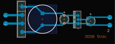
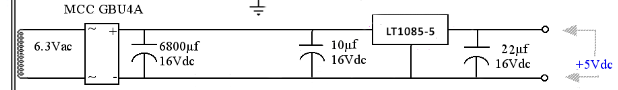
Do you think this would be better? I won't use the hammond I'm gonna use taps from my transformer. I got it from this forum: https://diyaudioprojects.com/Forum/viewtopic.php?p=20091#p20091LT1085 needs 150uF output capacitance to be stable, unless you go for tantalum.
Attachments
Yes that would be better, don't forget to add two diodes over the regulator chip. one from adjust to output and one from output to input.
Also rectifier diodes you could try a bridge consisting of SB530 or 1N5828 or those have lower forward voltage than a normal bridge
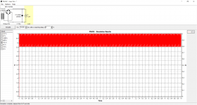
LT1085 dropout is around 1.2V so you need 6.2V minimum under the ripple of rectification to make this work from a 6.3V winding.
PSUD2 shows you dont get there with that 4A bridge. I took 1n5400 to simulate that 4A bridge and im getting 5.5V under the ripple with 6800uF If i change this to SB560 and 15000uF we get the required 7V under the ripple.
Another option is the MIC5156 regulator IC. I have boards for those. Feel free to use the schematic as you see fit. Ive updated the mosfet to IRL540N. The MIC5156 really makes a nice scalable regulator IC for DC power supplies. The only downside is the added complexity for the mosfet drive voltage. Ive added gerbers for the boards im selling to this post if you want to use these.
Shameless self advertising, swapmeet post can be found here: https://www.diyaudio.com/community/...6-based-tube-amp-upgrade.382265/#post-7113502
Also rectifier diodes you could try a bridge consisting of SB530 or 1N5828 or those have lower forward voltage than a normal bridge
LT1085 dropout is around 1.2V so you need 6.2V minimum under the ripple of rectification to make this work from a 6.3V winding.
PSUD2 shows you dont get there with that 4A bridge. I took 1n5400 to simulate that 4A bridge and im getting 5.5V under the ripple with 6800uF If i change this to SB560 and 15000uF we get the required 7V under the ripple.
Another option is the MIC5156 regulator IC. I have boards for those. Feel free to use the schematic as you see fit. Ive updated the mosfet to IRL540N. The MIC5156 really makes a nice scalable regulator IC for DC power supplies. The only downside is the added complexity for the mosfet drive voltage. Ive added gerbers for the boards im selling to this post if you want to use these.
Shameless self advertising, swapmeet post can be found here: https://www.diyaudio.com/community/...6-based-tube-amp-upgrade.382265/#post-7113502
Attachments
- Home
- Amplifiers
- Tubes / Valves
- 300B Board design rating