From the diagram below, there appears to be a connector that allows for bias to be measured.
Am I correct that to do that I need to remove the jumper (I will check the board tomorrow morning) and connect an DVM between those point (set to amps) to measure the current?
The VR allows the bias current to be set - can anyone tell me what this should be?
Am I correct that to do that I need to remove the jumper (I will check the board tomorrow morning) and connect an DVM between those point (set to amps) to measure the current?
The VR allows the bias current to be set - can anyone tell me what this should be?
Attachments
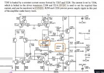
That is NOT a jumper. It is a two pin connector for a DVM to be plugged in,
or at least to which the DVM probes are to be affixed, to measure a DC voltage.
Do not short the two pins. They are for probing a DC voltage only.
Since you have the service manual, it should list the proper DC voltage, which corresponds
to the proper emitter current via the DC voltage drop across the two emitter resistors.
That manual is the only source of the proper biasing information.
Last edited:
Thanks for the clarification - I can see from the diagram the pins on the connector are not connected and go across the two 0.1 ohm resistors - doh!!!
Is is possible to tell from the circuit what voltage I can expect to see? (manual does not list ithe value)
Is is possible to tell from the circuit what voltage I can expect to see? (manual does not list ithe value)
The only proper way is to consult the service manual. Doing otherwise entails some risk of damage
or wrong operation. The amp could overheat, have excessive distortion, etc.
If absolutely no other information is available, some would adjust for 26mV across each emitter resistor.
That would be a reading of 52mV at the connector. But this would be unlikely to be exactly what
Cyrus specifies for the amp.