Hello!
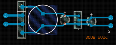
I need some advice on building this 300B, I have made the case but need recommendations on top and bottom plate of my case for the electronics(I was thinking brass). Also would like your input on how I should do the wiring, I have made the layout for parts and wiring. In the attached files there are the schematics and layouts. Cheers!
I need some advice on building this 300B, I have made the case but need recommendations on top and bottom plate of my case for the electronics(I was thinking brass). Also would like your input on how I should do the wiring, I have made the layout for parts and wiring. In the attached files there are the schematics and layouts. Cheers!
Attachments

Brass is pretty expensive. I would just go with 5052 aluminum sheet.I need some advice on building this 300B, I have made the case but need recommendations on top and bottom plate of my case for the electronics(I was thinking brass).
jeff
I would choose a slightly more traditional layout, but I understand everyone has their own ideas on how the layout should look, and that's ok.
jeff
jeff
I have a huge transformer and I dont really know how to stop all the magnetic fields interfiring and what to put whereI would choose a slightly more traditional layout, but I understand everyone has their own ideas on how the layout should look, and that's ok.
jeff
How about the layout in Stephe's video? Just an example as I haven't watched this particular build.
jeff
jeff
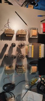
I have watched this but the problem is I have 4 chokes and my power transformer is bigger, Look. So do I put the chokes in the amp? How should I orient my chokes and where to put the tubes? I was thinking about putting the cokes underneath the top, put the 300B infront of the output transformers, put the 5UGB4 Infront of the power transformer so the AC circuit is as small as posibble and put the input tubes 6SN7 infront next to the pot. I just found so much information about the hum and don't wanna make a mistake here 😛How about the layout in Stephe's video? Just an example as I haven't watched this particular build.
jeff
Attachments
Last edited:
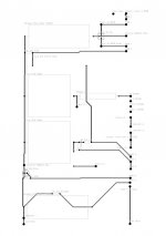
If you have 3 wire grounded power outlets, then use a 3 wire IEC cord, and a 3 wire IEC socket on the amplifier.
The AC from the IEC socket: Hot AC to the fuse, the fuse to the on/off switch, the on off switch to the power transformer primary, the other lead of the power transformer to the Neutral AC return. Connect the IEC ground directly to the chassis.
Safety First!
Prevent "The Surviving Spouse Syndrome"
Control the B+ Rectifier Ground Loop. Connect the B+ secondary center tap directly to the negative terminal of C6, first 47uF capacitor.
Then connect from there to the second filter cap negative terminal, C7 halves; and then from C7 to the central ground, (and the central ground of the amplifier has to connect to the chassis).
Insulate the RCA input connector from the chassis with shoulder washers. But then . . .
Connect the outer shell of the RCA input connector to R1 and C1 input tube self bias returns, and the return of P1. Then connect from there to the central ground point.
Connect the grid resistor return, and self bias returns of the driver tube, R2, R3 C2, to the central ground point. Connect C5 Return to the central ground point. Connect the returns of R5, R6, and C4 to the central ground point.
Last edited:
Well the schematic only has one 200H choke per channel, no I'm unclear as to why you have 4. And yes you can mount them underneath, but they should be rotated 45-90 degrees from any adjacent transformer.I have watched this but the problem is I have 4 chokes and my power transformer is bigger, Look. So do I put the chokes in the amp? How should I orient my chokes and where to put the tubes? I was thinking about putting the cokes underneath the top
jeff
You will notice:
The input loop, P1, R1, and C1 form a local ground loop.
And the B+ secondary center tap and C6 form a local ground loop.
Those loops are local, and Then after that, they connect to the central ground point (and the cental ground is connected to the chassis).
The other grounds loops like grid and cathode resistors & bypass caps are connected separately to the central ground point.
Do not connect local loops to each other, connect them separately to the central ground point.
The 5 Henry B+ chokes have the greatest magnetic field, Keep them far from the output transformers, and at right angles to the output transformers.
The power transformer is probably the next greatest magnetic field, keep them away from the output transformers, and at right angles to the output transformers.
The 20 Henry chokes need to be kept from the output transformers, and at right angles to the output transformers.
The video of Steph's amp shows a good example, and hopefully you can imagine the orientation of the coils of each of those parts.
It is the orientation of the coils that is the "at right angle" I am talking about.
Or, you can look at the laminations and see what is the proper right angle orientation I am talking about.
Good luck on having a low hum, low distortion amplifier that sounds great!
Be sure to put bleeder resistors across the B+ to drain the B+ down when the amp is unplugged and worked on.
Safety First!
Prevent "The Surviving Spouse Syndrome"
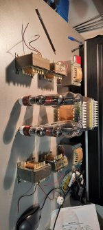
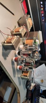
Here is my article on my build of Kevin' push-pull 300B design. I aimed for the Audio Note look with copper top plates, but went for aluminium with copper-coloured paint, as Al is much easer to work with (and a lot cheaper!) than Cu. The mains and output transformers are mounted on top of the top plate, and there are a couple more transformers and chokes underneath it. I didn't install bottom plates, partly for air circulation, partly for convenience, but that does make these heavy units uncomfortable to lift!
Alex
Alex
Are you read Vinylsavor (Thomas Mayer) blog?
http://vinylsavor.blogspot.com/sear...0+01:00&max-results=20&start=30&by-date=false
http://vinylsavor.blogspot.com/sear...0+01:00&max-results=20&start=30&by-date=false
The lamination thing I want to ask you about. If there is a proper angle between them can they be closer?You will notice:
The input loop, P1, R1, and C1 form a local ground loop.
And the B+ secondary center tap and C6 form a local ground loop.
Those loops are local, and Then after that, they connect to the central ground point (and the cental ground is connected to the chassis).
The other grounds loops like grid and cathode resistors & bypass caps are connected separately to the central ground point.
Do not connect local loops to each other, connect them separately to the central ground point.
The 5 Henry B+ chokes have the greatest magnetic field, Keep them far from the output transformers, and at right angles to the output transformers.
The power transformer is probably the next greatest magnetic field, keep them away from the output transformers, and at right angles to the output transformers.
The 20 Henry chokes need to be kept from the output transformers, and at right angles to the output transformers.
The video of Steph's amp shows a good example, and hopefully you can imagine the orientation of the coils of each of those parts.
It is the orientation of the coils that is the "at right angle" I am talking about.
Or, you can look at the laminations and see what is the proper right angle orientation I am talking about.
Good luck on having a low hum, low distortion amplifier that sounds great!
Be sure to put bleeder resistors across the B+ to drain the B+ down when the amp is unplugged and worked on.
Safety First!
Prevent "The Surviving Spouse Syndrome"
Last edited:
- Home
- Amplifiers
- Tubes / Valves
- 300B first build