This is an older mod I did to a Yamaha CA-810 to stop its preamp from picking up FM radio. Finally got around to posting it for someone who asked for the schematic.
I live a half-mile from a strong FM transmitter. Here, a fair fraction of vintage preamps will pick it right up -- it bleeds through audibly into the output. This was one.
Usually, increasing stability margins of the gain stages will fix it. I'm fond of using two-pole compensation for this: generally you can lower the unity loopgain frequency, and obtain much more generous stability margins, without sacrificing any in-band feedback or changing the sound of a preamp. A ULGF below 10MHz generally means the circuit simply cannot operate at 100MHz, not actively.
These are the mods for the CA-810:
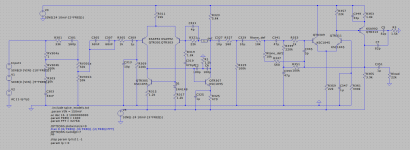
- Delete C311
- Replace C321 with 4p
- Replace C323 with a 1.5k / 100p / 100p TPC network as shown in the schematic. This is C2, C6, and R1 on the schematic.
- Replace R325 with 470 ohms. (This may not be strictly needed to improve stability, but it lifts TR305 out of quasi-saturation, which makes me trust spice to better model this circuit and surely helps with distortion performance.)
- For the 2nd gain stage after the tone controls, add a 1.5k / 82p / 82p TPC network from the collector to the base of TR313. This is C5, C7, and R3 on the schematic. This transistor had no miller cap before, but it benefits from some compensation from collector to base.