Hi All,
Stumbled across this on youtube and thought to ask what everyone thinks of the design? Schematic and details

I may have got a little excited and ordered some 6n13s tubes... And I have to say thats a gloriously pretty build!
Stumbled across this on youtube and thought to ask what everyone thinks of the design? Schematic and details
I may have got a little excited and ordered some 6n13s tubes... And I have to say thats a gloriously pretty build!
The video is a speaker amp - there's no HPA. However that depends on the headphones you're driving - I assume 600R ? It will have a high impedance output compared to modern solid state HPAs. The issue is that you will have a lot of power for what is <100mW typically to reach 120dB. If it is a stereo amp for speaks then you will find it needs some tweaks.
Also no output coupling means if the tube shorts then you could have ±160V on your headphone. You could add, say, 3200uF non-polar on the output to decouple. Also if you short the output then it may draw excessive current from both rails through the output tubes (as it warns 8R min).
Would also prefer to use an attenuator rather than a volume pot with the signal if it's a HPA as you will hear details/noise easier with sensitive headphones. The volume pot is essentially a carbon film resistor.
Last edited:
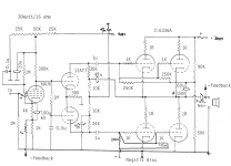
There something wrong with the schematic.
The plate voltage of the upper section of the 6N6P is indicated as 355 V. So the current through the upper section would be (405 - 355) / (15K + 4K7) = 2.5 mA. The current through the lower section of the 6N6P can't be far off, so lets say the total current of the two sections is 5 mA.
But 5 mA means that the voltage drop over the shared cathode resistor of 4K7 would only be 0.005 x 4K7 = 23.5 V.
The plate voltage of the 6J4P is indicated as 88 V. The 6J4P is dc-coupled to the 6N6P.
This would mean that the cathode voltage of the 6N6P sits at a somewhat higher voltage than 88 V.
So conflicting outcomes...
My guess is that the value of 4K7 of the shared cathode resistor of the 6N6P is wrong since its value is very low for a long-tail pair.
Yeah, I'm downloading the .asc now and planning on having a look-see if there's any differences. <edit> Between the lt spice schematic and values in the published schematic.
One point - if you make a AC coupled output you can treat each pair of tubes individually for biasing but you will find caps are inside the feedback.
I'm ok with that. This is a fun/learning exercise with an outcome I can listen to. Caps inside the feedback loop are ok for me.One point - if you make a AC coupled output you can treat each pair of tubes individually for biasing but you will find caps are inside the feedback.
Does it come in a kit? (I'm not interested in the kit just that if it's your first tube amp then having all the correct rated components is one less thing to worry about).
I would try a shorted tube on your .asc and a shorted headphone connection. Also check the peak to peak output as speaker amps will have a larger swing than a low impedance headphone for example.
You really want an output decoupling for safety after the feedback. Just ensure there's a 10K resistor to ground on the headphone side or you may have a nasty surprise. There's more safety thinking required for headphones..
Not my first, and not a kit. I've made a few valve amps and sand amps and I'm not short of parts either... I'm all good to have a shot at it, and I'm ok with the risk factor. I'll give your suggestions a shot - thats good advice.
Noted on the decoupling also!
Noted on the decoupling also!
The author had referenced the below links in one of his comments as references for the design.
http://www.asahi-net.or.jp/~cn3h-kkc/claft/6as7otl.htm
http://www.furo-visu.com/s_otl/6AS7_otl.html
http://www2u.biglobe.ne.jp/~hu_amp/6080otl.htm
I've redrawn the original schematic in lt spice and it makes a bit more sense now. I'll post when I get home.
http://www.asahi-net.or.jp/~cn3h-kkc/claft/6as7otl.htm
http://www.furo-visu.com/s_otl/6AS7_otl.html
http://www2u.biglobe.ne.jp/~hu_amp/6080otl.htm
I've redrawn the original schematic in lt spice and it makes a bit more sense now. I'll post when I get home.
- Home
- Amplifiers
- Tubes / Valves
- OTL Amp design from youtube - Headphone and Power Amp. Thoughts?