Hi all,
I have just finished building some three-way speakers & to go with them, I have been trying to fix my NAD 3020B - with little luck. It has been to a technician twice and sadly has blown up directly after getting it back both times. It has had a full recap & new transistors/resistors on both channels - however this does not seem to have fixed anything as it keeps failing. The first time it blew - R903 was smoking. The second time (after the tech first repaired it) it was R651, and this time around it was Q614 that was smoking. Since then, I have built a dim bulb tester & taken it into my own hands to try to diagnose / fix it.
I have once again replaced any transistors that have bad readings / ones that i thought might be at fault (Q609, Q610, Q612, & Q614) & i have also added 0.33 ohm resistors on the emitters of the output transistors (as I read this was necessary on a few forums about old NADs). I am, however, still stuck with no sound on the right channel & upon turning it on most recently (after swapping out the output transistors again), I was greeted with a loud crackle/buzz from both speakers that does not fade (perhaps something wrong with grounding). Meanwhile, the dim-bulb is lit (but is not very bright) - suggesting a short somewhere.
What would you all try next? Any & all advice is very appreciated.
Thanks in advance
P.s. I would prefer to get to the bottom of this myself, but if this fails, I would also be open to suggestions re. good technicians near Melbourne, Vic.
Attachments
Update: I have eliminated the buzz/hum in both channels. Now the problem is still just no sound coming from the right channel.

I'm not exactly sure, but I cleaned around the output transistors and tightened their screws.What was the buzz?

Update: Having just probed a few things, I now have sound in both channels, but only from the mids/subwoofers. The mids & tweeters are popping a little and otherwise, the tweeters are just hissing (in both channels). It is no longer the low Hze buzz that I had before.
What does this suggest? I am confused. :/
What does this suggest? I am confused. :/
Why not take it back to stock by taking out those emitter resistors fault find then mod if you need to.
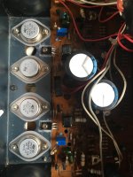
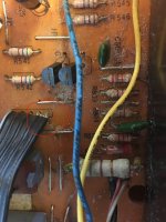
Also is the lead of one of the white resistors touching the screw?
Need to redo the soldering properly around the output transistors as well.
What's the bias set at?
What does the dc offset measure?
Also is the lead of one of the white resistors touching the screw?
Need to redo the soldering properly around the output transistors as well.
What's the bias set at?
What does the dc offset measure?
Last edited by a moderator:
I wouldn't take the emitter resistors out with modern output transistors. The resistors are needed to make the thing stable with modern Epitaxial transistors.Why not take it back to stock by taking out those emitter resistors fault find then mod if you need to.
The buzzing would suggest oscillation though
I wouldn't take the emitter resistors out with modern output transistors. The resistors are needed to make the thing stable with modern Epitaxial transistors.
The buzzing would suggest oscillation though
Are the modern version of those transistor numbers different specs from what was in it originally?
Yes. The original transistors used by NAD were Hometaxial types. This allowed them to "get away" with no emitter resistors. With modern Epitaxial devices, the amp goes into thermal runaway.Are the modern version of those transistor numbers different specs from what was in it originally?
Ah like the Quad 303?Yes. The original transistors used by NAD were Hometaxial types. This allowed them to "get away" with no emitter resistors. With modern Epitaxial devices, the amp goes into thermal runaway.
Yes - I believe the amp overheated both times after the repairs because the tech had not added the emitters after replacing the hometaxial types. Although on taking the outputs out after the second repair, I found a ball of solder in whole that was maybe causing a short. However, addressing these two things has not seemed to have helped.
The lead on the resistor is not touching the screw & i cannot see a bridge anywhere otherwise. It is just the angle of that photo I think.
I have just given the board a good clean & I will do the soldering properly now around the outputs to see if that helps.
Offset is sitting at about -10mv & the bias is at 60mv - I tried to get this lower (aiming for 30), but i have maxed out the variable resistors I put in there (so i thought I would ask here to get to the heart of the channel/buzz issue first).
Hi all,
I am moving this thread over to Audio Karma so that all the info is in one place.
https://audiokarma.org/forums/index.php?threads/nad3020b-repair.1007131/#post-15877642
Thanks so much for the replies so far.
I am moving this thread over to Audio Karma so that all the info is in one place.
https://audiokarma.org/forums/index.php?threads/nad3020b-repair.1007131/#post-15877642
Thanks so much for the replies so far.
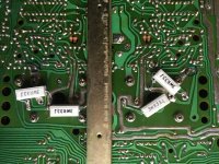
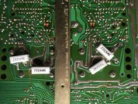
I'm incredibly glad to say I found the short with a little bit of percussion. A wire on this ribbon (JLA3 - pictured, circled in red) was crossing with the one beside it. Sound is clear as can be now. Now to sort out the channel problem and I should be there.
Thanks for the input all!
Thanks for the input all!
Attachments
Last edited:
That so-called "technician" who putzed around with this unit must have gotten his education from "I work for a paycheck only" school.
Or maybe he learned his trade off the internet blogs.... LOL!
Sadly, there are many of those creeps out there who don't know crap about repairs and proper diagnosing problems.
Or maybe he learned his trade off the internet blogs.... LOL!
Sadly, there are many of those creeps out there who don't know crap about repairs and proper diagnosing problems.
I think I'd try and move those emitter resistors to reside on the topside of the PCB for better thermal management....
The lead on the resistor is not touching the screw & i cannot see a bridge anywhere otherwise. It is just the angle of that photo I think.
I have just given the board a good clean & I will do the soldering properly now around the outputs to see if that helps.
...
Hi all,
I've just used an RCA cable to bridge L-R and R-L at the Pre-amp out & Normal in.
Now, with the pre-amp bridged, the right channel is working - so it would appear the problem is the pre-amp & that I don't need to worry about the output transistors again.
I have fixed the ribbon, but I am still struggling to find the fault causing sound in only one channel. would anyone be able to tell me some key things to check in the pre-amp section?
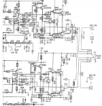
I have traced voltages across the unit and both channels appear to match. Is there something obvious that might be faulty stopping sound in one channel? I was curious about maybe Q509-510, or perhaps BD901 (although i'm not quite sure of the process of testing this component). Stumbling in the dark now.
I've just used an RCA cable to bridge L-R and R-L at the Pre-amp out & Normal in.
Now, with the pre-amp bridged, the right channel is working - so it would appear the problem is the pre-amp & that I don't need to worry about the output transistors again.
I have fixed the ribbon, but I am still struggling to find the fault causing sound in only one channel. would anyone be able to tell me some key things to check in the pre-amp section?
I have traced voltages across the unit and both channels appear to match. Is there something obvious that might be faulty stopping sound in one channel? I was curious about maybe Q509-510, or perhaps BD901 (although i'm not quite sure of the process of testing this component). Stumbling in the dark now.
- Home
- Amplifiers
- Solid State
- NAD 3020B