Hi, I wanted to build a discrete version of the LM4562 op amp following zubr's drawing of its internal schematic (link). However, I'm having trouble getting it stable. Maybe someone who has more experience on amplifier compensation than me can help me.
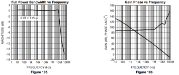
There is always a resonance at 20 to 40 MHz, which - even if the loopgain looks fine - leads to full or partial instability in the square wave test. I think it is visible in the datasheet's phase plot as well, but there it is tamed down (see attached images).
Some observations:
Any help is appreciated.
There is always a resonance at 20 to 40 MHz, which - even if the loopgain looks fine - leads to full or partial instability in the square wave test. I think it is visible in the datasheet's phase plot as well, but there it is tamed down (see attached images).
Some observations:
- The datasheet loopgain has knees at around 10 Hz and 1 MHz suggesting a compensation capacitor in the 100 pF range.
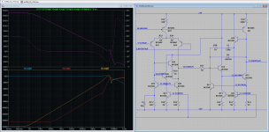
- Replacing the emitter follower buffered current mirror with a different type notably changes the phase response.
- I'm not sure about the role of Q6 (zubr's schematic). Normally it's off, suggesting it's role is protection related. Removing it has some influence on loopgain still. There is the option to remove its emitter resistor, but therefore either increase the VAS emitter resistor or reduce the current mirror degeneration resistors. zubr noted he wasn't sure if it has an emitter resistor or not.
Any help is appreciated.
Attachments
-
LM4562_discrete.zip1.7 MB · Views: 302
-
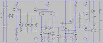 LM4562_internal_zubr.png13.8 KB · Views: 476
 -
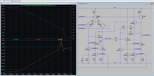
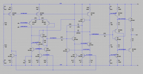 LM4562_ltspice.PNG28 KB · Views: 485
 -
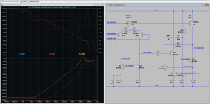
 LM4562_GainPhase.PNG49.3 KB · Views: 321
 -
 LM4562_01_Full.PNG41.9 KB · Views: 320
 -
 LM4562_02_DifferentMirror.PNG40 KB · Views: 279
 -
 LM4562_03_VAS.PNG40.9 KB · Views: 265
 -
 LM4562_04_VAS2.PNG138.9 KB · Views: 369
I hawe solved unstabilitys with this fast opamps with triple power supplay decopling, with double decopling are they not stable.
bmtas
bmtas
Looks like Q6 and D7 are there for better clipping, not for small signal performance. If this guess is correct, then Q6 needs no emitter resistor, just as D7 does not need one in series. If you leave Q6 out, you may need to add back some capacitance between the collectors of Q1 and Q2.
The instability may be related to the diamond buffer at the output - emitter followers like to see their source impedance fall with frequency. To check if that’s correct, connect the right end of C2 to the collector of Q8 instead of the emitter of Q10, or add a small capacitance between the collector of Q8 and ground or one of the supply rails, or add small capacitors between the base and collector of each of Q13 and Q14. The capacitance of D8 and D9 may be part of this, too. The resulting amplitude and phase response may be somewhat different from the original, but you will have a clue as to where to look further.
The instability may be related to the diamond buffer at the output - emitter followers like to see their source impedance fall with frequency. To check if that’s correct, connect the right end of C2 to the collector of Q8 instead of the emitter of Q10, or add a small capacitance between the collector of Q8 and ground or one of the supply rails, or add small capacitors between the base and collector of each of Q13 and Q14. The capacitance of D8 and D9 may be part of this, too. The resulting amplitude and phase response may be somewhat different from the original, but you will have a clue as to where to look further.
Last edited:
Thank you for your suggestions. I tried those, but without much success. I still ran into the problem that the phase plot looks fine, but square wave test doesn't pass.
I also came to the conclusion that I violate the premise of the LM4562 - not to load the VAS - when connecting capacitors directly to the output of the VAS and/or circumventing the integrator buffer. I wouldn't be building a LM4562 anymore.
I tinkered around further and as it turns out, the Cordell BC550C just doesn't work in the VAS. So does the NXP BC850 or BCP68 model. Very much all other transistor models that I now tried can be made stable. Replacing all or only the VAS transistors with the Cordell 2N3904 or 2N2222 and increasing the VAS currents works rather well. So is using slower diamond buffer output transistors (BD139/BD140) or slowing them down with capacitors as suggested by alexcp. This gets you rid of some last resonances at around 100 MHz.
Clever as I am I left out the protection diodes at the output and input, but they only seem to change things in the 100 MHz to 1 GHz regime.
The small 20 MHz blip in the phase response of the datasheet seems to be related to generating the currents with an emitter follower enhanced mirror. Using a plain two transistor mirror removes it.
Now it's time to make it robust against layout 🙂
Output is getting little warm so added small heatsink , today I'm testing on headphone and it's sounds AWSM 😁

- Home
- Source & Line
- Analog Line Level
- Discrete LM4562 / LME49710 / LME49720 compensation help needed