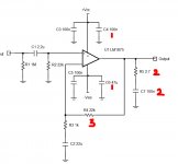
Hi I am building LM1875 amplifier, Transformer Will be 18-0-18V and source CD Player (Occassional Phono Pre). I understand lm1875 IC Datasheet has standard values for broad application. But I wanted to know in Chipamp.com BrianGT schematic (See pic attached) why values of
1) C4 and C6 values are 0.1uf and 47 uf instead of standard 100uf and 100uf*
2) Zobel network R5 and C7 are 2.7ohms and 0.1uf instead of 1 ohm and 0.22uf **
3) feedback resistor R4 is 22k instead of standard 20k.
*Powersupply will probably be with snubber capacitors and MUR860 diodes. Do suggest what type of capacitor will be good.
**my speaker wires will be short and speakers are not decided. Probably wideband.
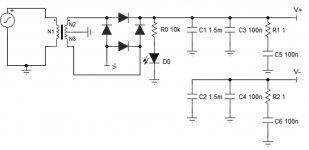
power supply schematic also attached.
Thanks and regards
1) C4 and C6 values are 0.1uf and 47 uf instead of standard 100uf and 100uf*
2) Zobel network R5 and C7 are 2.7ohms and 0.1uf instead of 1 ohm and 0.22uf **
3) feedback resistor R4 is 22k instead of standard 20k.
*Powersupply will probably be with snubber capacitors and MUR860 diodes. Do suggest what type of capacitor will be good.
**my speaker wires will be short and speakers are not decided. Probably wideband.
power supply schematic also attached.
Thanks and regards
Attachments
I believe there was no 'special' reason to bypass datasheet recommendations!
1) If you are going to use separate power supply board then 0.1uf plus 100uf close to pwr supply pin is more reasonable.
2) Although not critical but the zobel RC must be 'empirically' sized(by means of observation or experience rather than theory or pure logic).There must be some reason for choosing 1ohm plus 0.22uf as zobel. Because 2.7R/ 4.7R/ 10R resistor plus 0.1uf cap is more common. I suggest datasheet values.
3)Probably for desirable gain setting 🙂
If you're going to use loads lower than 8ohm then slightly lower power supply voltage is better. I recommend 15-0-15 150VA transformer for stereo. For reservoirs caps, 2x6800uf 35v standard low esr electrolytics are more than enough! *(without any decoupling or snubber) Wish you success!
Last edited:

thanks,
Reason for 18-0-18 was for occassional loud listening a little less chance of clipping. Though I guess broad values will work but still would like to know reasons.
regards.
Reason for 18-0-18 was for occassional loud listening a little less chance of clipping. Though I guess broad values will work but still would like to know reasons.
regards.
Suggest Following the Datasheet 'suggested' Schematic. You won't do better by deviating from it.
1875 makes for a decent Computer /desktop speaker Amp Or for a smallish Bedroom setup.
It's a good Amp , but not spectacular sounding either.... despite claims by fanboys.
Proof of this is in the hearing.. G'luck.
1875 makes for a decent Computer /desktop speaker Amp Or for a smallish Bedroom setup.
It's a good Amp , but not spectacular sounding either.... despite claims by fanboys.
Proof of this is in the hearing.. G'luck.
This is my 4.5th* budget diy amp to keep myself busy and learn. I am not expecting hugh difference or sound levels. I have not deviated from the values of datasheet. The pic I posted is of BrianGT lm1875 chipamp from chipamp.com. I was only curious for the reasons behind different values from designer and his thinking. Datasheet will not tell me that.
Component counts for the amp are very less. So was interested in types (Standard, Metal film resistors, MLCC, Film etc caps) of components too. No desire to buy premier stuff just a level above the standard components. Since this is DIY need to try different things. In earlier builds I have used chinese components too.
*a tube amp project was abandoned for lack of budget output transformers.🙂
regards
I think i already answered your questions, but still if you are not satisfied then it's better to ask BrianGT personally (or look into his thread).
Best regards
Best regards
Hello everyone,
Two questions
1) Will quarter watt resistors do for this amp ? (except R5 ofcourse)
2) Can I use MLCC capacitor at C2 (22uf) as non polar is not easily available here?
thanks.
Two questions
1) Will quarter watt resistors do for this amp ? (except R5 ofcourse)
2) Can I use MLCC capacitor at C2 (22uf) as non polar is not easily available here?
thanks.
What I meant was wattages for rest of the resistors apart from R5.1)1/4watt resistor for R5 is fine! 2)You can use bipolar electrolytic there, easily available. Use 47-100uf at least.
any sources for Bipolar electrolytic india ?
are bipolar electrolytic different from non polar ?
regds
Seems like an error on C4, it should also be 47uF as on the neg rail.Hi I am building LM1875 amplifier, Transformer Will be 18-0-18V and source CD Player (Occassional Phono Pre). I understand lm1875 IC Datasheet has standard values for broad application. But I wanted to know in Chipamp.com BrianGT schematic (See pic attached) why values of
1) C4 and C6 values are 0.1uf and 47 uf instead of standard 100uf and 100uf*
2) Zobel network R5 and C7 are 2.7ohms and 0.1uf instead of 1 ohm and 0.22uf **
3) feedback resistor R4 is 22k instead of standard 20k.
*Powersupply will probably be with snubber capacitors and MUR860 diodes. Do suggest what type of capacitor will be good.
**my speaker wires will be short and speakers are not decided. Probably wideband.
power supply schematic also attached.
Thanks and regards
Other differences depending on judgement of the designer, they are minor.
Jan
OK. thanks. will use 47uf
For capacitor voltages rating I will use double rating for the voltages any particular capacitor will see. For ex in C4 it will see 25v so I will use voltages above it as 35v to 50 or 63 v. correct ?
Dont know how to calculate wattage of resistors used. R5 (Zobel) since at output will see maximum current so chipamp.com said 2W. but dont know about rest of the resistor ratings.
regds
LM1875 gets super hot beyond +/-20VDC at 4R, if I were you I would stick to +/- 12VDC to +/-15VDC. Thermal induced distortions ,hotspots and reduction in output current would be major concern beyond that.
as said in first post this will mostly be used with wideband driver. at moderate to low volume levels.LM1875 gets super hot beyond +/-20VDC at 4R, if I were you I would stick to +/- 12VDC to +/-15VDC. Thermal induced distortions ,hotspots and reduction in output current would be major concern beyond that.
regds
I know. But why exception for R5? If 1/4watt is enough for R5 then of course for rest of the amplifiers! You can even use 1/8watt for feedbacks. But 1/4watt is good for thermal noise perspective! You can also use 1w throughout if you wish to, but that costs & for very minor improvements! Anyway i recommend using fuse type, non flammable resistor for R5. People use higher wattage resistors there due to fear of oscillations! But i think differently....What I meant was wattages for rest of the resistors apart from R5.
Look at RS components. Diyaudiocart is also good. Recently i purchased some MUSE & Elna RBD for my 3886. Good & cheap.any sources for Bipolar electrolytic india ?
Of course not.are bipolar electrolytic different from non polar
Exactly! & that is what i recommended in my first post. Not to use more than +/-20vDC! also the difference between 20w & 25watt isn't huge! Btw i still wondering about his comment on clipping 🤔LM1875 gets super hot beyond +/-20VDC at 4R, if I were you I would stick to +/- 12VDC to +/-15VDC. Thermal induced distortions ,hotspots and reduction in output current would be major concern beyond that.
Sorry not to be clear. this will mostly be used for single driver speaker not going low on impedance. Listening levels would also be not high. Higher voltage in long run will protect from music peak which may be 4 times higher and reaching rail voltage and resulting in clipping. Will probably give long life to speakers. (High sensitivity bookshelf is last option if things dont work out and if so lower voltage will be choosen.)
Note : Transformer and speakers are not yet finalised. will see if anyone loans transformer/speakers to practically see after I make the amplifier.
regds
Note : Transformer and speakers are not yet finalised. will see if anyone loans transformer/speakers to practically see after I make the amplifier.
regds
You're thinking too much without being clear on your goal !!...also to answer your question(which is kinda vague) we need to know about many thing, like what kind of music do you like? what is the sensitivity of your speaker? load impedance...etc etc & i think you are confused between "Crest factor" & Clipping. Crest factor directly related to device SOA!
https://neurochrome.com/pages/thermal-design#ThermalDesignExample2
On the other hand if you want maximum voltage swing into higher impedance load for momentary peaks then +/-25vDC is at low side, I'll go for +/-28vDC(max). Btw how expensive speaker you are going to use with this $35 worth amplifier?! there are many spkr protection kit available in the market.
Regards
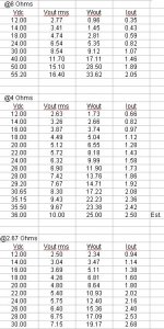
I had saved this chart for reference purpose, courtesy - measurements done by a diyaudio member
PS measurments done by @johnr66
As Jan pointed out, probably a typo. There isn't much meaningful difference between 47 uF and 100 uF in that spot. Personally, I would add 1000 uF where the power enters the amplifier PCB - at least if you're using a separate board for the power supply. The extra bulk capacitance reduces the effect of the inductance of the power supply wiring.1) C4 and C6 values are 0.1uf and 47 uf instead of standard 100uf and 100uf*
Be careful with ceramic caps for the decoupling capacitors. Some ceramic dielectrics have horrid voltage coefficients (i.e., their capacitance drops significantly when voltage is applied). Same for temperature coefficient. 100 nF is commonly available in C0G/NP0 which has practically zero voltage and temperature coefficient, so I'd go with that. But 47-100 uF pushes you into X5R, X7R, etc. I wouldn't expect a 100 uF, X7R capacitor to provide more than about 20 uF if it's charged to more than half its rated voltage. Check the data sheet for the capacitor to be sure. I'd go with an electrolytic cap in that spot.
That's roughly the same time constant (tau = RC), so no practical difference. 2.7 Ω would present a lighter load on the amp at RF. Maybe that's gentler on the IC. 100 nF is a very common capacitor value, so maybe that's why the designer used it.2) Zobel network R5 and C7 are 2.7ohms and 0.1uf instead of 1 ohm and 0.22uf **
So the gain will be 1+22/1 = 23 instead of 1+20/1 = 21. That's a 20*log10(23/21) = 0.8 dB difference. Nothing substantial.3) feedback resistor R4 is 22k instead of standard 20k.
Many designers, me included, use the E12 standard resistor values: 10,12,15,18,22,27,33,39,47,56,68,82. You'll notice that 20 is not in there. That doesn't show up until E24: 10,11,12,13,15,16,18,20,22,24,.... It's mostly just a habit, but also E12 values tend to be in stock whereas E24 aren't always.
Electrolytic ones...*Powersupply will probably be with snubber capacitors and MUR860 diodes. Do suggest what type of capacitor will be good.
I would connect the LED from V+ to V- so it discharges both rails.power supply schematic also attached.
Tom
- Home
- Amplifiers
- Chip Amps
- LM1875 Amplifier - Change in Component values.