Hi
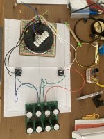
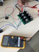
If possible, i would like some advices on a transformer to bridge rectifier to filter caps PCB connections.
I have upgraded a tube amp in the past, done a Noir amplifier, now tackling a M2x and would like to check my wirings and most important my understanding (would go through a workmate who is knowledgeable but a bit too much as for him "everything is easy/super simple, just plug the damn thing" 😵).It is part of my learning process.
Attached is a PDF showing the different parts, my understanding of the connections i did, and some pictures in addition to the pdf.
Here is my main interrogation / where i need your knowledge for proper understanding.
a. I was worried that, maybe i would have connected the bridge rectifier wrongly and they could give me an inverted wave form, hence i could be cancelling out the power when connecting them to the filter cap PCB.
Different websites /Youtube videos seems to give different connections but not exactly for the same type of configs. (Youtube DIY Audio Implementers has 2 trans to feed the filter caps PCB)
Yet, come to think about it, since the rectifier redress the wave forms (no alternance anymore), it shouldn't matter. No need to care too much, just connect the transfer to any AC lug and get the "+" to the correct side of the filter cap PCB.
That's where i am a bit at loss and would like a bit of teaching/checking if possible.
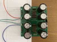
b. DIY audio powersuppply PCB was out of stock when i need to order. Instead I went to a surrogate that should be equivalent to old schematics. I have seen the same on different builds.
Is there anything i should check particularly? (if one knows)
Thanks in advance if you can help a bit.
At this point, i would tend to agree to Nelson Pass mentioning that SMPS power supply were easier for "new to DIYs"! (but i wanted more powerful than ACA...😏)

If possible, i would like some advices on a transformer to bridge rectifier to filter caps PCB connections.
I have upgraded a tube amp in the past, done a Noir amplifier, now tackling a M2x and would like to check my wirings and most important my understanding (would go through a workmate who is knowledgeable but a bit too much as for him "everything is easy/super simple, just plug the damn thing" 😵).It is part of my learning process.
Attached is a PDF showing the different parts, my understanding of the connections i did, and some pictures in addition to the pdf.
Here is my main interrogation / where i need your knowledge for proper understanding.
a. I was worried that, maybe i would have connected the bridge rectifier wrongly and they could give me an inverted wave form, hence i could be cancelling out the power when connecting them to the filter cap PCB.
Different websites /Youtube videos seems to give different connections but not exactly for the same type of configs. (Youtube DIY Audio Implementers has 2 trans to feed the filter caps PCB)
Yet, come to think about it, since the rectifier redress the wave forms (no alternance anymore), it shouldn't matter. No need to care too much, just connect the transfer to any AC lug and get the "+" to the correct side of the filter cap PCB.
That's where i am a bit at loss and would like a bit of teaching/checking if possible.
b. DIY audio powersuppply PCB was out of stock when i need to order. Instead I went to a surrogate that should be equivalent to old schematics. I have seen the same on different builds.
Is there anything i should check particularly? (if one knows)
Thanks in advance if you can help a bit.
At this point, i would tend to agree to Nelson Pass mentioning that SMPS power supply were easier for "new to DIYs"! (but i wanted more powerful than ACA...😏)
Attachments
-
 IMG_6358_DIY_PowerSupplyOverview.jpg525.6 KB · Views: 104
 -
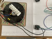 IMG_6361_ZoomTransfo_CL60_1Bridge.jpg441.7 KB · Views: 107
 -
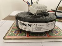 IMG_6360_ZoomTransforSpecs.jpg399.5 KB · Views: 104
 -
 IMG_6364_FilterCap_Oldmodel_BOTTOM.jpg369.8 KB · Views: 99
 -
 IMG_6363_FiltersCaps_OldModel_TOP.jpg424.2 KB · Views: 98
 -
DIY PowerSupply Assessment.pdf1.3 MB · Views: 76
diagram looks ok.
use some temporary fuses between tx/bridge bridge/caps or a bulb limiter.
https://www.diyaudio.com/community/threads/bulb-limiter-for-testing.252386/
use some temporary fuses between tx/bridge bridge/caps or a bulb limiter.
https://www.diyaudio.com/community/threads/bulb-limiter-for-testing.252386/
Hi.
Just to close the subject properly:
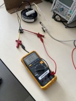
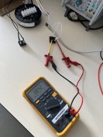
Did the check with somebody experimented. Works as intended with 18v after the rectifiers and around +/- 25v after the capacitors bank.
Maybe useful for somebody else later.
Regards
Just to close the subject properly:
Did the check with somebody experimented. Works as intended with 18v after the rectifiers and around +/- 25v after the capacitors bank.
Maybe useful for somebody else later.
Regards
Attachments

Hi.
Yes, i will.
I am planning to use a 400mm long chassis, but don't know yet the arrangement inside (where will the bridge rectifiers will be, capacitor banks...)
Hence the wire length was about having some flexibility before fixing everything & tidying up.
Chassis will take some time as i need to do the 3D for holes/cuts/screw thread positions & gather budget!
Have a nice day
That's the plan, especially with M2x and the need for power supply transformer and Edcor transformer to be far away.
Will see that with a cardboard or shoebox "prototype" but goal is to have 250mm width inside, no more because of other constraints outside (Mini Dissipante chassis planned for those constraints)
Will see that with a cardboard or shoebox "prototype" but goal is to have 250mm width inside, no more because of other constraints outside (Mini Dissipante chassis planned for those constraints)
- Home
- Amplifiers
- Power Supplies
- Need a bit of Help / Understanding regarding bridge rectifier connection between transfer and filter caps PCB