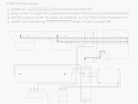
Why do people put capacitors on the GND/PWR tabs of small BT amplifiers? On some of my 5-6v setups there was a suggestion to put a capacitor on the VCC/GND terminals of the small amp itself, but i have never questioned it as it appears to work better with no brown outs/restarts.
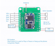
For example on using one of those CSR BT amp modules, it was suggested you put a 10v 2200uf capacitor soldered directly to the lead/terminals, yet on a recent build using similar parts it is now 10v 1000uf variant. Without it if i push the amp it will restart the BT component, but with it, it just pushes through no problem. So of course my mind starts to think what magic is this and how are they sized? These Chips also allow one to modify the on board EQ and filters, which made me wonder "could i size this capacitor and alter the EQ/Bass shelf without leading to saturation when pushed"
Its one of those items i've never questioned as it works, but currently looking for ways to refine the process, build and see what else i can do.
Attachments
The bulk power supply capacitance provides energy storage for when the amp needs to provide high current output. It is there to lower the impedance of the power supply (i.e., make it better at sourcing current).
Tom
Tom

Why do people put capacitors on the GND/PWR tabs of small BT amplifiers?
It's because the capacitor that should be there, is not there. Most likely because capacitors cost money, and money is expensive, so the seller decided it would be better for their bottom line if you bought the capacitor yourself.
It's because the capacitor that should be there, is not there. Most likely because capacitors cost money, and money is expensive, so the seller decided it would be better for their bottom line if you bought the capacitor yourself.
Also capacitors that stand "tall" gets damaged the way its posted by sites like aliexpress, in a bubble wrap envelope + without the caps they are easily stackable occupying small space
That's a really good point, actually. And it speaks volumes about the optimization the various eBay/Ali/Amazon sellers go through. They don't optimize for quality. Those of us who do spend the extra $1.60 for a quality shipping box.
Tom
Tom
Thanks all for the responses. I have a few different variants of these boards with different BT chips. They are perfect for my small portable speaker builds. One thing i wanted to look into was pushing the onboard DSP further and compensating for the additonal load potentially by using a properly sized cap
- Home
- Amplifiers
- Chip Amps
- Why do people put capacitors on the GND/PWR tabs...