I have an Audio Reasearch SP11 I got for a good deal in pristine condition the catch is it is missing the SP-11PS the power supply. Is there away to build a power supply for it? Thank you would like to here your suggestions..
https://www.arcdb.ws/model/SP11
https://www.arcdb.ws/Database/SP11/ARC_SP11_manual.pdf
They paid lots of attention to the power supply. Possibly see later models to take cues from later concepts.
https://www.arcdb.ws/Database/SP11/ARC_SP11_manual.pdf
They paid lots of attention to the power supply. Possibly see later models to take cues from later concepts.
Can you post some pictures, to see exactly what it needs?I have an Audio Reasearch SP11 I got for a good deal in pristine condition the catch is it is missing the SP-11PS the power supply. Is there away to build a power supply for it? Thank you would like to here your suggestions..
I am in the process (long delayed) of "repairing" my SP-11 power supply. One of the filament windings of the transformer failed. (I have heard that others have had issues with the power supply.) It's been an "off-and-on" project for years.
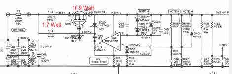
Their engineers relied upon the MOSFET to dissipate quite a bit of heat. Today you can chassis mount a 15W Ohmite 300 Ohm resistor for R112 to drop 39V ahead of the MOSFET. (Speaking of which, Tomchr (www.neurochrome.com) has a very nice HV regulator.) It's performance should far exceed the original AR design and it is quite compact. The more heat you can dissipate with the resistor, the less cumbersome the MOSFET heat-sinking becomes.
You may need two transformers -- AR ran the filaments of V3,4,5,6 in series (6DJ6) @12.7V. V2 is elevated filament, V1 run at 6.5V. Also need DC aux voltages for the soft-start.
Attachments
I am in the process (long delayed) of "repairing" my SP-11 power supply. One of the filament windings of the transformer failed. (I have heard that others have had issues with the power supply.) It's been an "off-and-on" project for years.
Their engineers relied upon the MOSFET to dissipate quite a bit of heat. Today you can chassis mount a 15W Ohmite 300 Ohm resistor for R112 to drop 39V ahead of the MOSFET. (Speaking of which, Tomchr (www.neurochrome.com) has a very nice HV regulator.) It's performance should far exceed the original AR design and it is quite compact. The more heat you can dissipate with the resistor, the less cumbersome the MOSFET heat-sinking becomes.
You may need two transformers -- AR ran the filaments of V3,4,5,6 in series (6DJ6) @12.7V. V2 is elevated filament, V1 run at 6.5V. Also need DC aux voltages for the soft-start.
I looked at the power supply schematic briefly. I can't find a data sheet for the MTM2N45 but apparently it came in a TO3 package which are pretty scarce these days. A re-engineered version would probably end up with a TO-220 which is even worse for heat sinking. But even with a big heat sink what would worry me in that design would be the SOA at start up. With 400 V on the input and 0 V on the output, even the relatively small output caps - I could only find 2 2 uF caps - would give you a pretty hairy trip through the SOA. (And forget about short circuit survival.)
Maybe you could use your idea of increasing R112 but instead of using one 300 ohm and a single big a$$ FET, divide the current up with say 4 75 ohm resistor/FET paths in parallel. That would give you power sharing but also pretty close to true SOA sharing.
Whoops 4 1200 ohm resistors, not 75 ohms as above. Bigger R to divide the current.Maybe you could use your idea of increasing R112 but instead of using one 300 ohm and a single big a$$ FET, divide the current up with say 4 75 ohm resistor/FET paths in parallel. That would give you power sharing but also pretty close to true SOA sharing.
The spec manual says 130watts max!! Thats alot for a preamp! heater requirements only come to about 4 watts total for 6 tubes. where is the other 126watts come from??
If You use ohms law, with a B+ of 304VDC with 126watts of power(discounting heater current) thats over 400mA of current for signal out??
If you divide 400mA between 12 individual triode thats over 30mA for each? Im thinking outloud here.
Hello vits,
I am coming back to this older thread as I am in the same situation with the PSU missing, did you finally diy/build your own psu at the end?
many thanks
I am coming back to this older thread as I am in the same situation with the PSU missing, did you finally diy/build your own psu at the end?
many thanks
I think that SP11's show up for sale with blown (or no) power supplies results from an under-spec'd transformer. I bought mine in non-working condition and one of the filament windings was shot.
There are now much better regulators for HV -- take for instance Jan Didden's TReg which is available from the DIYAUDIO store: https://diyaudiostore.com/products/linear-audio-t-reg
There are now much better regulators for HV -- take for instance Jan Didden's TReg which is available from the DIYAUDIO store: https://diyaudiostore.com/products/linear-audio-t-reg
- Home
- Amplifiers
- Power Supplies
- Audio Research SP11 power supply missing…can It be DIYed