I am going through the process of getting/finding my first adjustable and current limiting power supply. I have a linear fixed regulated 13Vdc supply and some SMPS blocks (18V etc) but I'm finding testing circuit ideas difficult without some controllable power (other than a lightbulb). I have a scope already so it's time to add a current limiting power supply at the cheaper end of the scale.
My requirements are simple - control at low power before moving up. To that end my requirements are:
I've actually now ordered two and received one already. The reason for this is that the Multicomp can only limit down to 250mA and that registered after it had shipped. I get the second tomorrow after which I will (highly likely) RMA the Multicomp Pro. However this gives a great opportunity todo some research with device in hand and pass on that knowledge for any other beginners. My money so this is not sponsored.
The supplies are:
My requirements are simple - control at low power before moving up. To that end my requirements are:
- Small - it needs to sit on a shelf next to the little DSO.
- 1-60Vdc allows me to test low voltage including
- floating power - this allows me to use a virtual ground as ±30 or ground as +60V or -60V.
- Output enable/disable switch
- Separate current and voltage dials.
- programmable power
- additional power ports
- USB SCPI port
I've actually now ordered two and received one already. The reason for this is that the Multicomp can only limit down to 250mA and that registered after it had shipped. I get the second tomorrow after which I will (highly likely) RMA the Multicomp Pro. However this gives a great opportunity todo some research with device in hand and pass on that knowledge for any other beginners. My money so this is not sponsored.
The supplies are:
- Multicomp Pro MP710081 (a rebadged Manson NTP-6561)
- Tenma 72-8340A
Multicomp Pro MP710081 (a rebadged Manson NTP-6561) firmware rEu1.1.
Facts
100W SMPS, slim and fandless (although the air slots are on the bottom and side so no packing it like a sardine beside other equipment).
1x controllable regulated current limited port - 0-60Vdc (actually 61V) and current limiting from 250mA to 1.6A (at 60V) with enable/disable switch.
1x 12Vdc regulated port that displays current draw as AUX1 on the screen (bottom right)
1x 3.3/5V regulated port that displays current draw as AUX2 on the screen (bottom right). There is a small switch on the back to switch between 3.3 and 5V.
Ports are floating and can be referenced to no ground but no ground port on the front - a ground screw at the back is available if a ground is needed.
Programmable power profile through, although a pain through the front dials it can be USB connected to the computer
SCPI USB port that supports voltage and current reads - which means you can plot voltage or current draw over time (slow not like a scope).
Comes with two shrouded alligator clips 1000V unbranded PVC plus a USB cable (with a ferrite).
A GitHub open source SCPI library for the Manson series PSUs that would work for this too (I've checked and it has model support).
Scores on the doors
+1 - Small, +1 - Noiseless.
+10 - 0-60Vdc
+10 - current limit, -15 for inconvenient 250mA lower limit.
+1 - constant voltage, constant current with clear indicators
+5 - floating port ground reference and those supplies can be stacked within the current limit (thus 60+12+5 = 77Vdc limited by the 5V aux current limit).
+1 - Enable switch with clear indicator, +1 voltage dial, +1 current dial
+1 - Pretty, clear read out for what is a cheap machine.
+1 - shrouded cross clips leads.
Bonus points
+3 - 12V aux 800mA/1.2A max, +3 - 2.2/5V aux ports, +1 - aux current readouts and they current limit to their max without drama. This makes it a rather good tube heater supply.. Switch on the back for the 3.3/5V would have been a -1 but there's a light on the front indicating 3.3 or 5V.
+1 - USB SCPI that features voltage and current readout plus programming a power profile.
= 25 points initial impressions.
First impressions.
It is both pretty, offers some really nice features .. but .. it's flawed in a big way for beginners.
Let's address the elephant in the room. It's minimum current limit is 250mA not 20mA not 1mA but 250mA. I mean - the device and form factor has market dominator written all over it, except for one small minor detail.. the daft current limit. That means blown LEDs or small devices for beginners. The entire MP71000xx range (including the 20V one) has a daft current limit minimum of 250mA..
My gut feeling is that the SMPS supply they use probably will have problems supplying current that low, either the switching drops into audible range or the components are large enough to cope with low rate or infrequent switching.
I've tested the voltages and current with two multimeters and the output vs displayed voltage/current seems spot on. Although I have noted to seems to take a short second to home in on the voltage. A good example is if you alter the voltage, there seems to be three display updates as the voltage drops to the set value.
Photos now and I'll put the scope on it.


Now - the Mrs just said you may as well keep it.. which means I now have two supplies 😀
Facts
100W SMPS, slim and fandless (although the air slots are on the bottom and side so no packing it like a sardine beside other equipment).
1x controllable regulated current limited port - 0-60Vdc (actually 61V) and current limiting from 250mA to 1.6A (at 60V) with enable/disable switch.
1x 12Vdc regulated port that displays current draw as AUX1 on the screen (bottom right)
1x 3.3/5V regulated port that displays current draw as AUX2 on the screen (bottom right). There is a small switch on the back to switch between 3.3 and 5V.
Ports are floating and can be referenced to no ground but no ground port on the front - a ground screw at the back is available if a ground is needed.
Programmable power profile through, although a pain through the front dials it can be USB connected to the computer
SCPI USB port that supports voltage and current reads - which means you can plot voltage or current draw over time (slow not like a scope).
Comes with two shrouded alligator clips 1000V unbranded PVC plus a USB cable (with a ferrite).
A GitHub open source SCPI library for the Manson series PSUs that would work for this too (I've checked and it has model support).
Scores on the doors
+1 - Small, +1 - Noiseless.
+10 - 0-60Vdc
+10 - current limit, -15 for inconvenient 250mA lower limit.
+1 - constant voltage, constant current with clear indicators
+5 - floating port ground reference and those supplies can be stacked within the current limit (thus 60+12+5 = 77Vdc limited by the 5V aux current limit).
+1 - Enable switch with clear indicator, +1 voltage dial, +1 current dial
+1 - Pretty, clear read out for what is a cheap machine.
+1 - shrouded cross clips leads.
Bonus points
+3 - 12V aux 800mA/1.2A max, +3 - 2.2/5V aux ports, +1 - aux current readouts and they current limit to their max without drama. This makes it a rather good tube heater supply.. Switch on the back for the 3.3/5V would have been a -1 but there's a light on the front indicating 3.3 or 5V.
+1 - USB SCPI that features voltage and current readout plus programming a power profile.
= 25 points initial impressions.
First impressions.
It is both pretty, offers some really nice features .. but .. it's flawed in a big way for beginners.
Let's address the elephant in the room. It's minimum current limit is 250mA not 20mA not 1mA but 250mA. I mean - the device and form factor has market dominator written all over it, except for one small minor detail.. the daft current limit. That means blown LEDs or small devices for beginners. The entire MP71000xx range (including the 20V one) has a daft current limit minimum of 250mA..
My gut feeling is that the SMPS supply they use probably will have problems supplying current that low, either the switching drops into audible range or the components are large enough to cope with low rate or infrequent switching.
I've tested the voltages and current with two multimeters and the output vs displayed voltage/current seems spot on. Although I have noted to seems to take a short second to home in on the voltage. A good example is if you alter the voltage, there seems to be three display updates as the voltage drops to the set value.
Photos now and I'll put the scope on it.
Now - the Mrs just said you may as well keep it.. which means I now have two supplies 😀

AC coupled. Top trace is the positive, the bottom trace is the negative grounded via scope ground lead.
1. No power

2. Powered up but no power enable (note voltage range increase):

3 - connect a 100W 8 ohm resistor load
3.a. Enabled 20V unlimited current (1.8A) - reads 10V 1.2A (no range changes)

3.b. Enabled 40V unlimited current (1.8A) - reads 14.45V 1.8A = 25W.. max current limit

3.c. Enabled 60V unlimited current (1.8A) - reads 14.45V 1.8A = 25W.. max current limit. Had a bit of a large AC wobble before settling down:


3.c. Enabled 10V 1.2A load limit set (as 10/8=1.2A) we should see 10V..
10V but then dropped a little to 9.79V at 1.2A, the multimeter shows 9.6V, changing the multimeter around this shows 1.9A too.

That is clear and seems common is that although the power supply is only outputting a small amount of noise through the positive, there is a fair amount of noise coming out from either the earth or the negative pin (I assume the earth which then shows up through the scope ground clip).
So it seems capable, although the 1.8A limit means you don't have a clear 60V into anything (ohms law), it does seem well behaved so far in terms of noise.
Next up switch on/enable on/off using the scope and a rolling trace.
1. No power
2. Powered up but no power enable (note voltage range increase):
3 - connect a 100W 8 ohm resistor load
3.a. Enabled 20V unlimited current (1.8A) - reads 10V 1.2A (no range changes)
3.b. Enabled 40V unlimited current (1.8A) - reads 14.45V 1.8A = 25W.. max current limit
3.c. Enabled 60V unlimited current (1.8A) - reads 14.45V 1.8A = 25W.. max current limit. Had a bit of a large AC wobble before settling down:
3.c. Enabled 10V 1.2A load limit set (as 10/8=1.2A) we should see 10V..
10V but then dropped a little to 9.79V at 1.2A, the multimeter shows 9.6V, changing the multimeter around this shows 1.9A too.
That is clear and seems common is that although the power supply is only outputting a small amount of noise through the positive, there is a fair amount of noise coming out from either the earth or the negative pin (I assume the earth which then shows up through the scope ground clip).
So it seems capable, although the 1.8A limit means you don't have a clear 60V into anything (ohms law), it does seem well behaved so far in terms of noise.
Next up switch on/enable on/off using the scope and a rolling trace.
So first just a single channel on positive rolling trace showing noise level when output enabled. The scope is AC coupled.

Next up a full current rise with DC rolling trace with a trigger set to pick up the rise. 14V at 1.8A across the 8R load:

You can see the time it takes to switch on, this also happens when you current limit at 250mA across a 8R load:

Next up - is a test to check if the multicomp sends power through the output on mains switch. A rolling trace with a 8R load. The supply has had chance to discharge before power on - the short answer is there's a little spike:

Next up is the ON(enabled, 1A limit)-OFF-ON and a slightly larger spike appeared:

Note those are with a 8R load present, zooming in shows two close spikes at 2.16V. These occur just as the firmware version is displayed:
Without a load, set to 60V - turned enabled shows 60V on the scope:

Then mains power switch off and you can see a slow discharge through the power ports:

A longer rolling curve confirms this! So NEVER assume a powered off supply is not providing power! Classic capacitor discharge. As this is not connected to the 8R load, this is a bleed off:

Next a 60V set, the PSU is discharged and powered on - it appears there's no 60V spike but interestingly the voltage reads 0.63V without an output enabled.. showing an electrolytic has started to climb back up.. but the scope shows 630mV mean on the power supply rails without the enable on. Perhaps the enablement mosfet used to switch leaks over 1/2 a volt when the power is set to 60V.

I'm not going to try a 60V enabled ON-OFF-ON as it's clear that the supply will still be discharging through bleed off as we've seen already.
So we can already see some issues of the cheaper supplies - power-on spikes and voltage present on the terminals after power off. 8R is a tough load for a power supply geared for 60V (it would refute 7.8A) with maximum limit of 1.8A regardless of the voltage set.
There is a 36V 3A model, and the 60V model with a 1.8A max current needs careful consideration. For example a MF A220 has ±35V rails into 8 ohms which is almost 4.5A peak - it's not going to provide that much power (162W+) but for initial testing it will do as long as the load high enough to limit the current draw. Now two power supplies could be set to provide 2x higher current at 60V.. or the same small current at 120V as long as the load is high enough.
So no other gremlins to report other than the expected SMPS noise. It should be noted that these supplies don't follow a current limit that takes into account the voltage. Hence you get 1.8A limit regardless if it's 1V or 60V (into a 36.6R load would give 1.6A - it's quoted max) and that 100W into a 1R load doesn't result in a 10A at 10V..
One of the first tasks of these power supplies will be to power up and test a LT3080 regulator (20Vdc) and a maida LT3080 regulator (170Vdc). So these will prove helpful on the initial work and help as I scale up the regulator. The 170V supply powers a 20mA tube, so this is where a 250mA limit is bad and where the natural resistance of the tube will help the power supply get to 60V during the testing. Thinking about it - the 12V could power a tube heater or two and the AUX2 5V could almost be used to power a rectifier tube heater (1.8A limit).
The aux supplies aren't connected to the main supply and as such on power up they are both powered during the startup sequence irrespective of the output enable. They have the exact same capacitor discharge on power down.
Over the next few weeks I will have a play with the USB side of things, although starting a new job will damp the hours I have to play. Tomorrow the second power supply should arrive.
Next up a full current rise with DC rolling trace with a trigger set to pick up the rise. 14V at 1.8A across the 8R load:
You can see the time it takes to switch on, this also happens when you current limit at 250mA across a 8R load:
Next up - is a test to check if the multicomp sends power through the output on mains switch. A rolling trace with a 8R load. The supply has had chance to discharge before power on - the short answer is there's a little spike:
Next up is the ON(enabled, 1A limit)-OFF-ON and a slightly larger spike appeared:
Note those are with a 8R load present, zooming in shows two close spikes at 2.16V. These occur just as the firmware version is displayed:
Without a load, set to 60V - turned enabled shows 60V on the scope:
Then mains power switch off and you can see a slow discharge through the power ports:
A longer rolling curve confirms this! So NEVER assume a powered off supply is not providing power! Classic capacitor discharge. As this is not connected to the 8R load, this is a bleed off:
Next a 60V set, the PSU is discharged and powered on - it appears there's no 60V spike but interestingly the voltage reads 0.63V without an output enabled.. showing an electrolytic has started to climb back up.. but the scope shows 630mV mean on the power supply rails without the enable on. Perhaps the enablement mosfet used to switch leaks over 1/2 a volt when the power is set to 60V.
I'm not going to try a 60V enabled ON-OFF-ON as it's clear that the supply will still be discharging through bleed off as we've seen already.
So we can already see some issues of the cheaper supplies - power-on spikes and voltage present on the terminals after power off. 8R is a tough load for a power supply geared for 60V (it would refute 7.8A) with maximum limit of 1.8A regardless of the voltage set.
There is a 36V 3A model, and the 60V model with a 1.8A max current needs careful consideration. For example a MF A220 has ±35V rails into 8 ohms which is almost 4.5A peak - it's not going to provide that much power (162W+) but for initial testing it will do as long as the load high enough to limit the current draw. Now two power supplies could be set to provide 2x higher current at 60V.. or the same small current at 120V as long as the load is high enough.
So no other gremlins to report other than the expected SMPS noise. It should be noted that these supplies don't follow a current limit that takes into account the voltage. Hence you get 1.8A limit regardless if it's 1V or 60V (into a 36.6R load would give 1.6A - it's quoted max) and that 100W into a 1R load doesn't result in a 10A at 10V..
One of the first tasks of these power supplies will be to power up and test a LT3080 regulator (20Vdc) and a maida LT3080 regulator (170Vdc). So these will prove helpful on the initial work and help as I scale up the regulator. The 170V supply powers a 20mA tube, so this is where a 250mA limit is bad and where the natural resistance of the tube will help the power supply get to 60V during the testing. Thinking about it - the 12V could power a tube heater or two and the AUX2 5V could almost be used to power a rectifier tube heater (1.8A limit).
The aux supplies aren't connected to the main supply and as such on power up they are both powered during the startup sequence irrespective of the output enable. They have the exact same capacitor discharge on power down.
Over the next few weeks I will have a play with the USB side of things, although starting a new job will damp the hours I have to play. Tomorrow the second power supply should arrive.
Last edited:
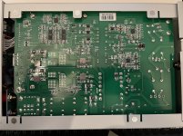
Channelling my best Davey "Don't switch it on, take it apart!"

It's interesting that the "Engine" above is rated for 60V 10A...


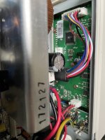
The front panel:

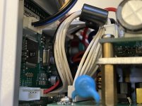
Interesting it has a TX/RX pair - it already has one of these to the left (with the blue/yellow/white/black) labeled TX/RX that connects to the back USB board.
Hidden at the top is this - this is a PIC programming port allowing you to read/write the chip including downloading the code from FLASH:

All the screen printing makes it easy to see what is going on - including the large white connector on the main board that tells you the purpose of each of the wires going to front display/control board.
Apart from the CrapXOn (CapXOn) caps which are low quality, the design seems relatively decent. I suspect the Capri X caps are also the favoured Chinese low cost producer as it seems to be prevalent on most Chinese produced boards. However the amount of tech packed in for the price I'm not surprised.
It looks like you get some components (engine) shared with many of the other Manson line however the components are lower quality/lower specced. The amount of inductors to keep it all clean was quite surprising. They certainly have packed it in. Now if only I knew why they set a lower limit of 250mA it may be able to reverse engineer and reprogram the microcontroller for low minimum limit..
It's interesting that the "Engine" above is rated for 60V 10A...
The front panel:
Interesting it has a TX/RX pair - it already has one of these to the left (with the blue/yellow/white/black) labeled TX/RX that connects to the back USB board.
Hidden at the top is this - this is a PIC programming port allowing you to read/write the chip including downloading the code from FLASH:
All the screen printing makes it easy to see what is going on - including the large white connector on the main board that tells you the purpose of each of the wires going to front display/control board.
Apart from the CrapXOn (CapXOn) caps which are low quality, the design seems relatively decent. I suspect the Capri X caps are also the favoured Chinese low cost producer as it seems to be prevalent on most Chinese produced boards. However the amount of tech packed in for the price I'm not surprised.
It looks like you get some components (engine) shared with many of the other Manson line however the components are lower quality/lower specced. The amount of inductors to keep it all clean was quite surprising. They certainly have packed it in. Now if only I knew why they set a lower limit of 250mA it may be able to reverse engineer and reprogram the microcontroller for low minimum limit..
Attachments
Last edited:
Hmmm "Programmable" isn't entirely correct. Looking at the SCPI commands in the operating manual and trying them out:
This shows you can get/set the functions over the USB port using a simple 9600 baud serial terminal over USB. The PIC on the front panel then implements your commands. Unfortunately you can't tell it to set a smaller current limit over USB unfortunately as the PIC controller knows it's 250mA coded minimum.
So I suspect the windows CD program provides the control and UI then behind the scenes it schedules SCPI commands immediately as time progresses on the computer. There's no programmable preset memories on this model (although the PIC microcontroller can do that). You could do the same with python and pySerial.
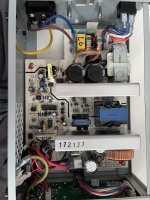
The PowerEngine seems to be components designed by a small HK design org, PowerELab, that creates SMPS components that can be plugged together like lego by customers. Hence I think the inside is modular with the other Manson range. When you look at this model half the components aren't populated on the engine PCB.
It uses a differential pair across a current sense resistor for the output current and provides that to the ADC on the PIC controller.
I suspect the engine is a simple implementation just made to look complex by the boards but the components aren't populated. It looks like a PFC into a DC link then it has a set of buck converters to drop from DC to DC for final regulation.
Typically buck etc shouldn't have problems providing a minimum current level below 250mA, after all the power supply can be operated without load on the outputs which implies no load thus no current and so the PWM would be at the minims or in sleep.
Code:
CURR0200
OK<0D>
GETS
500;250;<0D>OK<0D>
This shows you can get/set the functions over the USB port using a simple 9600 baud serial terminal over USB. The PIC on the front panel then implements your commands. Unfortunately you can't tell it to set a smaller current limit over USB unfortunately as the PIC controller knows it's 250mA coded minimum.
So I suspect the windows CD program provides the control and UI then behind the scenes it schedules SCPI commands immediately as time progresses on the computer. There's no programmable preset memories on this model (although the PIC microcontroller can do that). You could do the same with python and pySerial.
The PowerEngine seems to be components designed by a small HK design org, PowerELab, that creates SMPS components that can be plugged together like lego by customers. Hence I think the inside is modular with the other Manson range. When you look at this model half the components aren't populated on the engine PCB.
It uses a differential pair across a current sense resistor for the output current and provides that to the ADC on the PIC controller.
I suspect the engine is a simple implementation just made to look complex by the boards but the components aren't populated. It looks like a PFC into a DC link then it has a set of buck converters to drop from DC to DC for final regulation.
Typically buck etc shouldn't have problems providing a minimum current level below 250mA, after all the power supply can be operated without load on the outputs which implies no load thus no current and so the PWM would be at the minims or in sleep.
Next up is the Tenma 72-8340A (same 60V 1.6A 1.8A max).
Tenma 72-8340A (again a rebadged Manson) firmware rEu1.7. This shares an almost identical outside/format however inside it varies from the Multicomp - being older/less complicated but sharing a large amount of architecture and layout.
Facts
100W SMPS, slim and fandless (although the air slots are on the bottom and side so no packing it like a sardine beside other equipment).
1x controllable regulated current limited port - 0-60Vdc (actually 61V) and current limiting from 150mA to 1.6A (at 60V) with enable/disable switch.
Terminals are floating and can be referenced to no ground with a ground port on the front direct to chassis ground.
Comes with no leads.
Scores on the doors
+1 - Small, +1 - Noiseless.
+10 - 0-60Vdc
+10 - current limit, -10 for less inconvenient 150mA lower limit.
+1 - constant voltage, constant current with indicators but not as clear as the multicomp.
+5 - floating port ground reference but no real indication to what level (the SMPS will have a limit at some point), perhaps a +60V float would work.
+1 - Enable switch with clear indicator, +1 voltage dial, +1 current dial
+0 - Not as clean or clear as the multicomp.
= 21 points initial impressions.
First impressions.
This looks older and the insides also confirm this is an older/simpler design. It uses the same switching dual push-pull mosfet/half bridge configuration, the same microchip controller sits on the front board but the boards are different, specifically on the output voltage control. It looks like the Tenma uses a voltage regulator but the multicomp uses a more complex design.
The 150mA limiting is better than the multicomp but not able to dial down to 10mA for example.
The voltages seem good, along with the current limiting. It has a different noise profile on the scope but they both have noise on the output.
Attachments
I will update over time but an initial use for these so far:
1. Regulator testing from 1 to 60V.
This worked well allowing testing of the LT3080 from 1 to 32Vdc before adding the maida. Components to test up to 60Vdc with an appropriate load showing no issues before migrating the maida regulator to the unregulated 177Vdc PSU.
2. Testing hybrid circlotron BJT stability.
Complex with the two supplies floating on opposite sides of the load - essentially providing an adjustable 1-32Vdc supply the the BJTs. The two HV 177Vdc for the tube then sits on top of the LV supplies for the tube triode which sees 177+22 or 32V. The entire lot floats around the single ground point.
This is where I noted that the multicomp failed to provide a current readout whereas the tenma read within 1.5mA compared to the DMM setup as an independent current meter. The multicomp was outputting current but not displaying it. It may be the multi comp can only read to 10mA vs the tenma that reads to ~1mA.
Perhaps the floating configuration (note supplies are close to 0V on their neg terminal but they could be sat slightly (ie mV) below 0V.
- Home
- Design & Build
- Equipment & Tools
- Beginner bench supply