Been through a number of iterations on developing a power amp for my stereo rig - most recently, a few months back I had a thread for a stereo SE amp built around the 807. I got as far as a crude prototype, but life intervened again. In the meantime, I found an eBay auction for an inexpensive pair of Hammond AO-39 chasses. These were reverb amps for the A100 organ, and have a 5U4-based power supply, two 6BQ5s in cathode-biased AB1, and a 12AX7. Hmmmmmm ... a pair of PP monoblocks with a little more power ... Hell yeah, I'm in!
The original circuit is built around a differential input, and is not really appropriate for a guitar power amp in a number of ways, so I designed a circuit with a Fender-esque LTP on the input and adjustable cathode bias for the power tubes. I chose to use the 6P14P-EV in order to run higher voltages (and dissipation, but as we'll see that wasn't an issue), and the 6N2P on the front end because I have a pile of them and I'd rather use my vintage ones in something where they'll make a difference.
I've successfully built the prototype, and am now stripping the chasses to prep for cleaning and painting. I may or may not reuse the noval sockets, depending on how easily they clean up (and whether I break them in the process).
Power Supply
The original power supply ran the rectifier into a dropping resistor and then to a CRC pi filter, taking the B+ from the second filter cap. This is overly complicated for my use case, so I simplified it to taking the B+ from the first filter cap. Removing 250R and using modern wall voltage raised B+ by 55V, to 370V, well within spec for these tubes. I chose 335V for the screen supply based on simulation results, and the the PI is fed a solid 300V. The 6.3V heaters will be elevated from the power tube cathodes. The 5U4 is running well within spec.

Phase Inverter
The PI is a standard Fender LTP. I think I cribbed the values from the Deluxe Reverb? Simulation showed that the 82/100 plate resistors were overcorrecting for the imbalance, so I changed to 91/100 and got very close. I think I also changed up the GNFB values.
There will be a 100k attenuator prior to the blocking cap.
Power Section
Bog-standard shared cathode bias EL84 power section. The only complication I added is a 2W 200R pot so that I can dial in the bias more closely when I change tubes. The pot goes to a 100R resistor to ground for bias measurement. I also added a 100K resistor around the pot for insurance - if the pot ever fails short, this will cut the tubes off instead of letting the bias get too hot. 470R screen resistors simulated the best balance between output and distortion. Oh, and I also built the simulation with a 16R load on an 8R transformer, because the Hammond OT wants a 4R load and I'll be using 8R cabs.

The only disappointment I've got is that due to the GNFB, it's got pretty low sensitivity. I may use a pot for it to be able to adjust sensitivity on the fly. OTOH, I'm also using a preamp that can easily drive the low sensitivity if necessary.
Specs:
5.4Vpp (1.9 Vrms, +8dbu) input yields 11W at 1% THD
7.6Vpp (2.7Vrms, +10.8dbu) input yields 14W at 5% THD (just getting into crossover distortion)
Frequency response +/- 1dB from 40Hz to 33kHz (limited by OT - the circuit simulates at +/- 0.5dB from 10Hz to 77kHz)
Output impedance ~1R in the audio range
Plate dissipation at idle: 12W
Screen dissipation at max output (14W/5%THD): 2W
I'll be posting pictures as I go to show how things are progressing. Would love to hear any thoughts on the circuit or the approach!
The original circuit is built around a differential input, and is not really appropriate for a guitar power amp in a number of ways, so I designed a circuit with a Fender-esque LTP on the input and adjustable cathode bias for the power tubes. I chose to use the 6P14P-EV in order to run higher voltages (and dissipation, but as we'll see that wasn't an issue), and the 6N2P on the front end because I have a pile of them and I'd rather use my vintage ones in something where they'll make a difference.
I've successfully built the prototype, and am now stripping the chasses to prep for cleaning and painting. I may or may not reuse the noval sockets, depending on how easily they clean up (and whether I break them in the process).
Power Supply
The original power supply ran the rectifier into a dropping resistor and then to a CRC pi filter, taking the B+ from the second filter cap. This is overly complicated for my use case, so I simplified it to taking the B+ from the first filter cap. Removing 250R and using modern wall voltage raised B+ by 55V, to 370V, well within spec for these tubes. I chose 335V for the screen supply based on simulation results, and the the PI is fed a solid 300V. The 6.3V heaters will be elevated from the power tube cathodes. The 5U4 is running well within spec.
Phase Inverter
The PI is a standard Fender LTP. I think I cribbed the values from the Deluxe Reverb? Simulation showed that the 82/100 plate resistors were overcorrecting for the imbalance, so I changed to 91/100 and got very close. I think I also changed up the GNFB values.
There will be a 100k attenuator prior to the blocking cap.
Power Section
Bog-standard shared cathode bias EL84 power section. The only complication I added is a 2W 200R pot so that I can dial in the bias more closely when I change tubes. The pot goes to a 100R resistor to ground for bias measurement. I also added a 100K resistor around the pot for insurance - if the pot ever fails short, this will cut the tubes off instead of letting the bias get too hot. 470R screen resistors simulated the best balance between output and distortion. Oh, and I also built the simulation with a 16R load on an 8R transformer, because the Hammond OT wants a 4R load and I'll be using 8R cabs.
The only disappointment I've got is that due to the GNFB, it's got pretty low sensitivity. I may use a pot for it to be able to adjust sensitivity on the fly. OTOH, I'm also using a preamp that can easily drive the low sensitivity if necessary.
Specs:
5.4Vpp (1.9 Vrms, +8dbu) input yields 11W at 1% THD
7.6Vpp (2.7Vrms, +10.8dbu) input yields 14W at 5% THD (just getting into crossover distortion)
Frequency response +/- 1dB from 40Hz to 33kHz (limited by OT - the circuit simulates at +/- 0.5dB from 10Hz to 77kHz)
Output impedance ~1R in the audio range
Plate dissipation at idle: 12W
Screen dissipation at max output (14W/5%THD): 2W
I'll be posting pictures as I go to show how things are progressing. Would love to hear any thoughts on the circuit or the approach!
Hammond's AO-39 wasn't the reverb amplifier, but the power amplifier in A-100 organs instead. It featured a 12AU7 as the balanced input stage. Anyway, you might have a search for the real reverb amp, which is called AO-35. Besides the 6BQ5 pair and the 5U4 rectifier, it features two small signal double triode, a 12AU7 and a 12AX7.
The reverb amp in later organs was the AO-44, with a pair of 6GW8's and a 6CA4 rectifier.
Cleaning Hammond tube sockets really is a PITA 😵! For whatever reason, Hammond opted for bending component and wire end leads several times around the lugs. It's an enormous mess to remove those without damaging the sockets!
Best regards!
Rather than a fancy rheostat in the cathode circuit, you can do a fixed resistor there and put a potentiometer to tap a portion of the voltage developed. End-stopper and wiper-failsafe easily added.a 2W 200R pot so that I can dial in the bias more closely when I change tubes. The pot goes to a 100R resistor to ground for bias measurement. I also added a 100K resistor around the pot

Oh right, I had them backwards for some reason. Which is weird, because I also have a complete AO-44 setup (including the tank) that I'm planning on making into a dedicated standalone reverb cabinet for my M3.Hammond's AO-39 wasn't the reverb amplifier, but the power amplifier in A-100 organs instead. It featured a 12AU7 as the balanced input stage. Anyway, you might have a search for the real reverb amp, which is called AO-35. Besides the 6BQ5 pair and the 5U4 rectifier, it features two small signal double triode, a 12AU7 and a 12AX7.
The reverb amp in later organs was the AO-44, with a pair of 6GW8's and a 6CA4 rectifier.
Cleaning Hammond tube sockets really is a PITA 😵! For whatever reason, Hammond opted for bending component and wire end leads several times around the lugs. It's an enormous mess to remove those without damaging the sockets!
Best regards!
Ugh, you're SO right on that. The worst are the boards in the AO-14/AO-29-style chassis - if you want to reuse them, you have to strip a million components that are all wrapped multiple times around the most fragile little tabs ever. That's why I'm considering just yanking the original noval sockets and using new ceramic ones I've got on hand.
That's an interesting topology that I wouldn't have considered. The only thing missing is the idle current test point, which in my circuit is provided by the 100R resistor. Would this be a good way to provide that?Rather than a fancy rheostat in the cathode circuit, you can do a fixed resistor there and put a potentiometer to tap a portion of the voltage developed. End-stopper and wiper-failsafe easily added.
View attachment 1082184
Attachments

Oh, what a good idea! It's about the same Hammond did in the M-100 and, of course, A-100 series. I'm sure you know that the reverb needs to be driven from the organs power amp output via the compression circuitry in the AO-35/44. Wish you a successful outcome!I'm planning on making into a dedicated standalone reverb cabinet for my M3.
Best regards!
Yep, I think I get how this is supposed to go - basically, tap the speaker output directly into the compressor input. I'll add an attenuator on the front end, so that I can use it at higher level inputs (e.g. from a guitar amp), and change the 1M trim pot (R7) to a knob for more control. Other than that, I'm going to leave the circuit as is. Fortunately, the person I got it from had already recapped it, so it should be fairly plug-and-play!Oh, what a good idea! It's about the same Hammond did in the M-100 and, of course, A-100 series. I'm sure you know that the reverb needs to be driven from the organs power amp output via the compression circuitry in the AO-35/44. Wish you a successful outcome!
Best regards!
Attachments
The voltage at top of the 200r tells the current? If you dislike fancy arithmetic while your tubes are melting, pre-compute the maximum and target voltages, or add a 1-Ohm at the bottom.The only thing missing is the idle current test point
The voltage at top of the 200r tells the current? If you dislike fancy arithmetic while your tubes are melting, pre-compute the maximum and target voltages, or add a 1-Ohm at the bottom.
Ah, I gotcha. So if I put a test point at the top of the 200R, I can measure the resistance to ground with the power off, then measure the voltage there and do the math to get to current. Something like that?
I'm not really allergic to math, but it seems like having a known resistance to ground in the circuit would make it easier to adjust on the fly, without having to re-measure the resistance after every adjustment. Or am I still missing something (a distinct possibility)?
Why? By inspection, the resistance should be 200||19,762 or 198 Ohms. 1% precision is not needed, though it has become fashionable. The 198 is NOT going to change enough to matter as you turn the 10k pot.I can measure the resistance to ground with the power off
Oh! I think I get where I'm confused now. The variable leg taps a portion of the cathode voltage and feeds it to the grid in order to adjust the bias. I think that's the part that I missed.Why? By inspection, the resistance should be 200||19,762 or 198 Ohms. 1% precision is not needed, though it has become fashionable. The 198 is NOT going to change enough to matter as you turn the 10k pot.
Am I at least closer to understanding?

Hey look, I finished a project!
Put these into service last night. I ended up sticking with my original "bias rheostat" idea, because I had a couple of wirewound 2W 200R trim pots on hand,
Here's what they looked like when I got them:

And here's what they look like now:

Input is the 1/4" jack on the right-hand side, output is installed into a plate covering the cap can holes (behind the rectifier). The test points are ground (black), bias (100R to ground, blue), and plate (red). Tubes are NOS 5C3S rectifier, NOS 6P14P-EV power tubes, and GE 12AX7s salvaged from an old Wurlitzer. I used new Dale CMF60 resistors throughout, mostly because I wanted long, stiff leads to work with. Coupling caps are all Illinois, electrolytics are Rubycon and Nichicon, input attenuators are Bourns, and the bias pots are NOS Clarostat. S-taper, no less!
The chokes are repurposed inductors from the Wurlitzer's tone-shaping filters; since they're only carrying screen and PI current, they're dropping about 5V and dissipating 45mW, so I felt comfortable sticking them in the power supply this way. The power inlet is a combined C14/fuse/lighted switch unit.
Performance was measured biased to 60mA idle cathode current (dissipating about 9.5W). I tapped off my 8R dummy load with alligator clips, split to my scope for power measurements, and my PC for distortion measurements. I used Pete Millett's Sound Card Interface running into the onboard Realtek interface, and audioTester 3.0, configured to ignore noise.
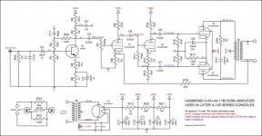
Here's the final as-built schematic. I'd include a gutshot, but like most point-to-point stuff I've done, it looks pretty messy (even though it's really not). Note that the schematic calls for 6N2P, and I used 12AX7 ... funny story behind that is that I accidentally wired the heaters for the 12AX7 by habit, and didn't notice until I was well into building the PI, which is kind of cramped and requires tricky lead routing. Rather than unwind that, fix the heaters, and redo it all, I decided that I'd just switch to using the 12AX7s I had on hand. Luckily the rest of the pinout matches, so I didn't have to redo anything!


Put these into service last night. I ended up sticking with my original "bias rheostat" idea, because I had a couple of wirewound 2W 200R trim pots on hand,
Here's what they looked like when I got them:
And here's what they look like now:
Input is the 1/4" jack on the right-hand side, output is installed into a plate covering the cap can holes (behind the rectifier). The test points are ground (black), bias (100R to ground, blue), and plate (red). Tubes are NOS 5C3S rectifier, NOS 6P14P-EV power tubes, and GE 12AX7s salvaged from an old Wurlitzer. I used new Dale CMF60 resistors throughout, mostly because I wanted long, stiff leads to work with. Coupling caps are all Illinois, electrolytics are Rubycon and Nichicon, input attenuators are Bourns, and the bias pots are NOS Clarostat. S-taper, no less!
The chokes are repurposed inductors from the Wurlitzer's tone-shaping filters; since they're only carrying screen and PI current, they're dropping about 5V and dissipating 45mW, so I felt comfortable sticking them in the power supply this way. The power inlet is a combined C14/fuse/lighted switch unit.
Performance was measured biased to 60mA idle cathode current (dissipating about 9.5W). I tapped off my 8R dummy load with alligator clips, split to my scope for power measurements, and my PC for distortion measurements. I used Pete Millett's Sound Card Interface running into the onboard Realtek interface, and audioTester 3.0, configured to ignore noise.
- 1W at 0.04% THD
- 10W at 1.03% THD from an 890 mVrms input
- 12.5W at 5.00% THD from a 1.21 Vrms input
Here's the final as-built schematic. I'd include a gutshot, but like most point-to-point stuff I've done, it looks pretty messy (even though it's really not). Note that the schematic calls for 6N2P, and I used 12AX7 ... funny story behind that is that I accidentally wired the heaters for the 12AX7 by habit, and didn't notice until I was well into building the PI, which is kind of cramped and requires tricky lead routing. Rather than unwind that, fix the heaters, and redo it all, I decided that I'd just switch to using the 12AX7s I had on hand. Luckily the rest of the pinout matches, so I didn't have to redo anything!
Last edited:
The datasheet has three different maximum Va:Those 6p14p ev are good at 370v?
- 300V for Pdiss > 8W
- 400V for Pdiss <= 8W
- 500V for "with lamp locked" (bad translation from Russian, I haven't been able to figure out exactly what that means)
They're also regularly used as substitutes for 7189A, which is good to 440V.
- Home
- Live Sound
- Instruments and Amps
- Monoblock based on Hammond AO-39