Hi all, Its been around few years since I've posted here and I'm hoping some much more knowledgeable members can once again give me guidance.
I have a valve PA amp that's been sitting collecting dust and finally opened it up, There's no circuit diagram available so I will have to trace this out, I have no problems with everything after the rectifier circuit, However, The rectifier circuit does have me bemused.
I'm not an electronics tech, But I do have a very healthy respect for high voltage, The amp has 5 valves, 1 x EF86, 2 x 12AX7, 2 x EL34, I believe the rectifier circuit may be half wave? 'but its how the diodes are connected that has me confused' (I've attached a photo).
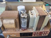
The AC input of neutral active & earth are not a problem, However, The Yellow wires in the photo are the high voltage secondary's with the green CT below the yellow wires soldered directly to ground.
One side of the high voltage secondary appears to be connected correctly through one diode to the first filter cap. The other half of the high voltage secondary is connected directly to the second pin of the first filter cap, The second diode has one leg connected directly to ground with the other leg connected to the first HV secondary mentioned above?
I can't wrap my head around this as to whether the rectifier circuit is a half wave or full wave rectifier circuit. The other colour wires coming out of the chassis are Blue = 6.3v heater, Green = CT for HV secondary, Brown = 240v mains in.
I've attached a photo of how the circuit is soldered in question
So my questions are
1 - Is the rectifier circuit half wave or full wave?
2 - How do I draw this out for schematic purposes, as I'm a bit dumbfounded by it?
other notes: I've not powered the amp up nor made any changes except cleaning off the build up of cobwebs and dust.
I hope someone can give me advice and guidance with this project.
cheers.
I have a valve PA amp that's been sitting collecting dust and finally opened it up, There's no circuit diagram available so I will have to trace this out, I have no problems with everything after the rectifier circuit, However, The rectifier circuit does have me bemused.
I'm not an electronics tech, But I do have a very healthy respect for high voltage, The amp has 5 valves, 1 x EF86, 2 x 12AX7, 2 x EL34, I believe the rectifier circuit may be half wave? 'but its how the diodes are connected that has me confused' (I've attached a photo).
The AC input of neutral active & earth are not a problem, However, The Yellow wires in the photo are the high voltage secondary's with the green CT below the yellow wires soldered directly to ground.
One side of the high voltage secondary appears to be connected correctly through one diode to the first filter cap. The other half of the high voltage secondary is connected directly to the second pin of the first filter cap, The second diode has one leg connected directly to ground with the other leg connected to the first HV secondary mentioned above?
I can't wrap my head around this as to whether the rectifier circuit is a half wave or full wave rectifier circuit. The other colour wires coming out of the chassis are Blue = 6.3v heater, Green = CT for HV secondary, Brown = 240v mains in.
I've attached a photo of how the circuit is soldered in question
So my questions are
1 - Is the rectifier circuit half wave or full wave?
2 - How do I draw this out for schematic purposes, as I'm a bit dumbfounded by it?
other notes: I've not powered the amp up nor made any changes except cleaning off the build up of cobwebs and dust.
I hope someone can give me advice and guidance with this project.
cheers.
Attachments
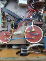
It is a full wave voltage doubler circuit. I have pasted a link that will show you the schematic. The tops of the capacitors in the schematic is the + terminal of the capacitor. I In your photo, the left capacitor + pin is at the top and on the right capacitor the + pin is on the bottom. Hope this helps.
Mickeystan
Mickeystan

Notice the clearance around the left cap. Caution, its can might be hot! Often there's a cardboard protector. That fell apart on one of my amps that uses this doubling scheme. I replaced it with a piece of PVC pipe, but didnt yet epoxy it to the can top surface - and managed to get tagged. Now it's epoxied...
Thank you kindly for this video Mickey, It explains it perfectly......I will still watch the video over a few times to make sure I have my head around.It is a full wave voltage doubler circuit. I have pasted a link that will show you the schematic. The tops of the capacitors in the schematic is the + terminal of the capacitor. I In your photo, the left capacitor + pin is at the top and on the right capacitor the + pin is on the bottom. Hope this helps.
Mickeystan
cheers.
Again, thank you kindly Mickey, This makes it much easier to understand.Please note that your right capacitor has two sections. The voltage doubler part of the power supply uses on the red and black terminal. The second have of the right capacitor is used as another section of RC filtering to smooth the B+ supply.
Mickeystan
Cheers.
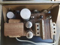
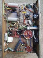
Here ya go. The chassis itself is really very small & compact 61/2 inch deep and 10inches wideI'm kinda interested in the rest of the amp--a PA amp with EL34s? That would be unusual, IMO. Can you post more pics?
Bit of birds nest underneath, But I'll be able to work through this especially with the replies from Mickeystan above.
Attachments

Same here in Australia Kevin, I don't know how many watts this amp is or will be?......I'm sure there will be some caps and resistors that will need to be replaced, Once I sort that out, I can then slowly bring it up on the Variac.Not that unusual in Europe, growing up I worked on a number of PA amps with a pair or quartet of EL34s for friends or school - all pentode mode, generally rated at 50W or 100W of output. The 100W amp ran plate voltages of around 600V as memory serves.
cheers.
Mickey, I believe this amp is 1960's vinatge judging by those old school/style rectifier diodes....Should replace those two straight up with modern diodes?Please note that your right capacitor has two sections. The voltage doubler part of the power supply uses on the red and black terminal. The second have of the right capacitor is used as another section of RC filtering to smooth the B+ supply.
Mickeystan
Osci, If it were mine, I would replace them with some 1a 1kv silicon parts. Even better are some ultra fast UF4007 1a 1kv parts. These are very reasonable to buy to. I would also replace the big electrolytic caps in the voltage doubler and 2nd. rc filter sections as they are obviously very old. If you choose to do this, play attention to the advice of properly insulating the outer can of the upper doubler capacitor as that can will be at one half of the rectified high voltage level. Good luck Mickeystan
Here ya go. The chassis itself is really very small & compact 61/2 inch deep and 10inches wide
Bit of birds nest underneath, But I'll be able to work through this especially with the replies from Mickeystan above.
Thank you! Interesting. I think in the US the 6L6 was much more common for PA service. Looks like a nice project!
Will do....once again, I much appreciate your advice.Osci, If it were mine, I would replace them with some 1a 1kv silicon parts. Even better are some ultra fast UF4007 1a 1kv parts. These are very reasonable to buy to. I would also replace the big electrolytic caps in the voltage doubler and 2nd. rc filter sections as they are obviously very old. If you choose to do this, play attention to the advice of properly insulating the outer can of the upper doubler capacitor as that can will be at one half of the rectified high voltage level. Good luck Mickeystan
+1Not that unusual in Europe, growing up I worked on a number of PA amps with a pair or quartet of EL34s for friends or school - all pentode mode, generally rated at 50W or 100W of output. The 100W amp ran plate voltages of around 600V as memory serves.
Are you sure that the green wire is the HV winding's CT? As this wire is grounded, that wouldn't make too much sense. I guess it's the heater winding's CT instead or the bias winding's gnd terminal..
Best regards!
Best regards!
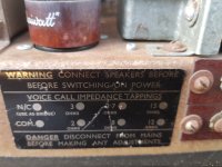
Even though the amp is from circa 1976, based on datecodes, its likely that all those e-caps are better replaced, unless you want to go through confirming they are each ok for leakage current at rated voltage.
Typical application would be as a guitar amp nowadays, but it would need some effort to make it safe and suitable. You may get some more insight from link on restoring such P amps: https://www.dalmura.com.au/static/Renovating PA amps.pdf
Typical application would be as a guitar amp nowadays, but it would need some effort to make it safe and suitable. You may get some more insight from link on restoring such P amps: https://www.dalmura.com.au/static/Renovating PA amps.pdf
It was the Standard here in Argentina, where we proudly feel European, with good reason.I'm kinda interested in the rest of the amp--a PA amp with EL34s? That would be unusual, IMO. Can you post more pics?
Our Electrical norms are DIN, we manufacture Mercedes Benz trucks and buses, Citroen, Renault and Fiat cars, etc. and used to have a humongous Philips factory, which among thousand other items locally made EL34.
While 6L6 was a specialty product, hard to find and expensive, and 6V6 directly unheard of.
I have about ten aussie PA amps using EL34/6CA7, so not uncommon. They were also used in aussie telco/radio line amps (such as the Trimax A54), and in niche products like the large regulated power supply from BWD 210B.
The tough aspect of the EL34 is that they can be difficult to swap out with other audio power valves due to the glass envelope size - and this thread's amp is no exception!!
The tough aspect of the EL34 is that they can be difficult to swap out with other audio power valves due to the glass envelope size - and this thread's amp is no exception!!
- Home
- Amplifiers
- Tubes / Valves
- Weird rectifier circuit with 2 diodes.