CH3/4 of this amp has an issue. I believe something wrong with the IRS2093M driver which is running CH1-4. CH5 is running from a pair of IRS2092.
Amp normally idles at 1.7A.
Ch3/4 under load works for the first few amps of pull up to about 7A, well before clipping, but then after that switches to massive oscilation and the amp will continue to draw 4A at idle. CH3/4 came to me stating not working. The amp is not going into protect, no shorted transistors from what I've tested. Amp will continue to work just fine on CH1-2 and CH5, and then CH3/4 will work again until over-drawn when power cycled.
IRS2093M... seems to be unavailable, and also not sure if my re-work station can handle replacing this component at this time.
Any advice?
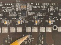
More info. The issue is actually only happening on CH3. I was originally bridging 3/4 and so I thought it was both.
CH3 pointed to by the pencil in the following photos.
CH3 pointed to by the pencil in the following photos.
Attachments
Do the ch3 FETs heat up?
How do the readings compare if you measure resistance on the output legs 1-2, 1-3 and 2-3 on all channels?
How do the readings compare if you measure resistance on the output legs 1-2, 1-3 and 2-3 on all channels?
Fet leg measurements are all about the same.
1-2: 2.6M~4.6M
1-3: 2.6M
2-3: 1k to 0.5M
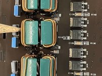
CH3 fets dont really heat up more than others under load. What is actually heating up are the large 4.7ohm snubber resistors near CH3 output coil my guess from the massive oscillation. I think thats why the amp starts drawing 4A at idle.
1-2: 2.6M~4.6M
1-3: 2.6M
2-3: 1k to 0.5M
CH3 fets dont really heat up more than others under load. What is actually heating up are the large 4.7ohm snubber resistors near CH3 output coil my guess from the massive oscillation. I think thats why the amp starts drawing 4A at idle.
It sounds like something is wrong with the output filter, either the inductor or the filter capacitors.
I checked through those components and I think they're all OK. Under 7A draw everything looks ok. Once it starts drawing harder its like the driver/IC or something else starts swinging very hard rail-to-rail or something like that. Only then does this cause the filter snubbers to overheat. I'll post some photos if I have the chance, but for now Im thinking its the IRS2093M which I may not be able to get. I may pass on servicing this one.
I swapped the inductor and 2 tiny filter caps and the problem is still in CH3. I also replaced the IRS2093M successfully but that didn't help either. CH3 still has much higher drive signal at terminals than the other 3 channels, Snubbers run so hot that they're getting discolored now but still measuring OK.
Any other thoughts?
Any other thoughts?
Drawing excessive current at idle and oscillation should tell you something. The only way for the output stage to draw current with no signal is to shoot through, or be just on the verge of shooting through. I believe if you scope the output FETs between the good and bad channels with a dual channel scope you may see both in the bad channel on at the same time, this can be a bad driver IC or possibly gate diodes if the amp has them.
What happens is the driver charges up the gates through the gate resistor but discharges them through the diode, and since the diode causes it to turn off faster than it turns on it helps avoid any potential overlap. If the diode is leaky or open it will instead discharge through the resistor and be on longer than it should be- sort of like shortening dead time which leads to excessive current in the affected channel. If the diode is shorted (more likely), then the driver will be trying to drive the gate through no resistance, which in and of itself is very likely to cause oscillations.
What happens is the driver charges up the gates through the gate resistor but discharges them through the diode, and since the diode causes it to turn off faster than it turns on it helps avoid any potential overlap. If the diode is leaky or open it will instead discharge through the resistor and be on longer than it should be- sort of like shortening dead time which leads to excessive current in the affected channel. If the diode is shorted (more likely), then the driver will be trying to drive the gate through no resistance, which in and of itself is very likely to cause oscillations.
110 looks like bootstrap stuff to me, more likely the ones sandwiched in there with the filter chokes. Beep it out from the individual gates to confirm and replace any in the bad channel, also try new FETs since the body diodes in those can sometimes be flaky as well. With the FETs out you may also get an opportunity to compare gate drive between the good and bad channels and see thing a little more clearly, since the oscillations are likely obscuring the actual square waves. If it doesn’t shut that channel down with them removed, that is.
- Home
- General Interest
- Car Audio
- JL Audio RD900/5 IRS2093M