Necessary to replace some resistors on a Yamaha...specs called for metal oxide on three of them...and metal film for a 1 ohm 1 watt. Not paying attention, I replaced the
specified metal film resistor with a metal oxide...same value- 1 ohm. Is it worth tearing into it again to replace that one resistor? Works fine. Sounds fine. Thanks...
specified metal film resistor with a metal oxide...same value- 1 ohm. Is it worth tearing into it again to replace that one resistor? Works fine. Sounds fine. Thanks...
So long as you used a 1-watt (or more) part for the 1-watt part, it should be fine.
Sounds like an output stage resistor - maybe a base stopper, or part of a Zobel network or decoupling network. In any of those cases, the super precise linearity of a metal film type isn't necessary at all.
Sounds like an output stage resistor - maybe a base stopper, or part of a Zobel network or decoupling network. In any of those cases, the super precise linearity of a metal film type isn't necessary at all.
Thank you. Not anxious to get in there again...no big deal..but there's always something to bend or short or disconnect...it's one of the amp boards on an RX v3000...
I do not know the function. It's from a Yamaha RX V3000 that would go into protect mode when switched on. I found two bad momentary switches on the front panel and a burned resistor on the f-amp board. It was one of a group of 4 resistors...three 15 ohm metal oxide and one metal film 1-ohm resistor. I elected to replace them all and mistakenly used a 1-ohm metal oxide resistor instead of the spec metal film. Not sure how that might affect the audio, but I figured Yamaha had a reason for specking it...but like I said..it seems to work
It appears these are related to -12V regulator IC356.
The 15R are all in series with its input, and the 1R is in series with its output.
I would think that the metal oxide would have better surge than the metal film.
The 15R are all in series with its input, and the 1R is in series with its output.
I would think that the metal oxide would have better surge than the metal film.
It is certainly rewarding and enlightening to converse with someone who knows circuit design and who is happy to share their knowledge. Thank you. As an aside comment, I have owned the Yamaha RX v2092, the 2095 and now the 3000. The Nichicon gold caps in the rx v3000 are a nice touch, and, I assume, an upgrade over the 92 and 95, but I have to say the soldering quality is not the best of the three...I have always believed Yamaha produced very good equipment, but the soldering of components on the 3000 is not the best. Reminds me of an NAD amp I ran across years ago...very surprised.
Are you talking about a surface mount board, or hand soldering? The SMT soldering can be deceptive,
as the solder is no-lead, and looks more dull. Or were there poor connection problems with it?
as the solder is no-lead, and looks more dull. Or were there poor connection problems with it?
Nope...talking about the 'hand soldering' if there is such a thing anymore...not the best I have seen...of course, this is a dinosaur receiver that has held up rather well over the years...so, must not be all that bad...but the solder joints on the resistors I replaced were toast...heat and age I suppose...although the RX V2095 is still going strong...I wish I could find a receiver built like my Sony DA5ES with a sound like my Yamaha...actually, a sound like my sansui 9090...had it since new and I haven't found anything like it for audio...well, nothing I wouldn't have to mortgage the house to afford.
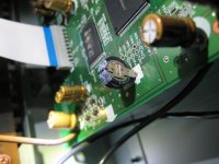
Sorry to pester you. But. Well, this is making me crazy. Or crazier. Silly memory capacitor...I've replaced them before...The arrow markings on the cap point to the negative lead, correct? Yet when I connect a voltmeter according to the markings, I get a negative voltage. Swap it around and I get positive voltage...WTH? Do I believe the voltmeter or the capacitor markings..???
Good question. Can you post a photo of the capacitor, is it like this one?
This one appears to have fat arrows pointing to the (-) terminal on the right side.
I would have to go with that.
Check your meter and leads by measuring a flashlight battery, and see what you get
for polarity.
This one appears to have fat arrows pointing to the (-) terminal on the right side.
I would have to go with that.
Check your meter and leads by measuring a flashlight battery, and see what you get
for polarity.
Attachments
Last edited:
Yep...that's the one...sorry for the delayed respose...I tried to respond immediately with an attachment but my computer is not it's old self...I had to get in and redo a lot of stuff...damned electrons are rude. But yes...that's the cap...you see the arrows point to the negative lead and the corresponding block on the PCB indicates that's where the negative lead belongs...that's the way mine is now installed. My confusion is that when I applied the voltmeter as a test to the cap negative to negative and positive to positive, I got a negative voltage reading...reversed the probes and got a positive voltage...didn't make sense...just trying to understand wth?.
Yes...the voltmeter is functional...I tried two of them...the leads are correctly into the meters by polarity...and a typical AA battery reads as it should. Who knows...everything seems to be working. Curious.
Yes, I did exactly that and all seems OK...still don't understand the meter reading. Thanks for the reply.
- Home
- Amplifiers
- Solid State
- Resistor question