Im trying to design my own chassis and am wondering what are some methods for hiding the faceplate mouting holes. If the aluminium was thick i suppose one could just thread the backside but im working with 5t thickness and thinner, preferably 3t if you could still do hidden screws there.
Thanks in advance.
Thanks in advance.

IF there are pots,jacks and similar, you can use their nuts to hold front panel.
Some push-in switches, pilot lights, etc.might do similar job.
Just one will be weak, but sharing the job between various components may do the trick.
Plan B: just glue the front panel to steel chassis.
Not kidding.
If that scares you, no need to use a very strong adhesive , there are weaker, water based ones,which never really dry but stay sticky forever, think sticky label type or speaker edge doping, they will securely hold front panel in place forever but if needed you slide a thin blade between panel and chassis to separate them.
I have used variations of this many times.
I make my own chassis and front panels, and silkscreen them.
Often make, say, 10-20 chassis (which is the harder work) but silkscreen 40-50 thin panels which is easy and cheap, them glue them on as needed.
If you're going to paint the panel you can use PEM screws. They press in flush with the front and give you a threaded screw out the back side. You need a press or a good machinist's vise with smooth jaws to seat them.
https://www.pemnet.com/fastening-products/studs-and-pins/
https://www.pemnet.com/fastening-products/studs-and-pins/
What's "5t" and "3t"?im working with 5t thickness and thinner, preferably 3t
This has worked well for me. Put studs in the handles so they can be attached with nuts between the heat sink fins. Most of the chassis, including the front panel, is made from an old macintosh computer case.A pair of handles à la rack mount could serve as faceplate fixing.
Attachments

Last edited:
Nice options thank you all!
Still looking for something easier to assemble which seems like it would be either some kind of hook/snap in from behind or flush screw for the torquing to happen from the front.
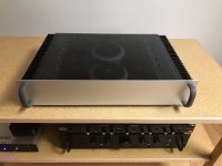
Incidentally just found out that diyaudiostore has the exact design i aspire to. I mean this thing is just beautiful...
https://diyaudiostore.com/collections/elekit/products/elekit-tu-8500
Still looking for something easier to assemble which seems like it would be either some kind of hook/snap in from behind or flush screw for the torquing to happen from the front.
Incidentally just found out that diyaudiostore has the exact design i aspire to. I mean this thing is just beautiful...
https://diyaudiostore.com/collections/elekit/products/elekit-tu-8500
SMSL mill a part of the face plate and put the screws there in recessed holes . Afterwards a plexiglass cover is glued inside of the milled area and that is 100% flush. Looks are quite nice but...it is very service unfriendly. While no screws or bolts are seen one has to remove the plexiglass cover slightly destructively.
Simplest is to use a thicker aluminium front cover and have thread in the backside of it.
Simplest is to use a thicker aluminium front cover and have thread in the backside of it.
Normal practice for minimum tapped hole depth is the diameter of the bolt plus one and and a half threads.
For the strength of the joint the weak point is not the bolt diameter but the yield strength of the panel engaging the threads. The normal back of the envelope calculation is the area of the bolt’s diameter times the yield strength of the panel material divided by three.
My feel is for a 5mm panel you could use an M2.5 .45 machine screw, but drilling the hole might shadow in the panel.
So an M2 might be better although you will need well more that four of them.
To drill a blind hole you can use a milling bit or for an amateur without much equipment start with a regular bit and then square the bottom with a milling bit.
You will also need a three tap set. One tap is a normal through hole tap. The second much less taper and the third has no taper. The third will cut threads all the way to the bottom of the hole.
Of course trying such a small tap will almost certainly result in tap breakage without lots of care and a proper tapping fluid. I would use “Tap Magic for Aluminum.” I also have a tapping head, but those are not exactly inexpensive!
3M VHB double-side tape, I guarantee that you will bend your faceplate/chassis getting it apart!
I've used the above stuff for a variety of applications (non-critical) and it holds far better and longer than expected. Good recommendation!
Alien Tape! "You'll Love It"™ LMAO
But seriously, you could wend or bond captive nuts to the back of the panel. I agree with JMFahey about gluing it, too. Just don't use an instant bonding glue because you'll want to be able to work with it to make sure it's in the right position.
But seriously, you could wend or bond captive nuts to the back of the panel. I agree with JMFahey about gluing it, too. Just don't use an instant bonding glue because you'll want to be able to work with it to make sure it's in the right position.
Captive nuts or L-brackets made of aluminum angle. Attach using J-B Weld. To bond aluminum to aluminum you can also use Alumiweld (basically, aluminum brazing rod). See my post about using Alumiweld here: https://www.diyaudio.com/community/threads/aca-concept.267517/#post-4244679
- Home
- Design & Build
- Construction Tips
- Chassis faceplate invisible screws