Hi there! been a while
A frind carpenter luthier have some little home based studio and he got some speakers somewhere. They are Polkaudio rt55i. he wanted to make a box and he can litterally make any box. Control room is little, like 6x9, but still the box could potentially be big and inside an insulating, non mechanically connected with studio, dry wall.
I took the meassurements, vas method didnt worked out well so had to make the mass one...
Any suggestions welcomed, this are supossed to go in ceiling. Was thinking about a TQWT with new front bafle.
And a question, where would one choose roll off to begin considering TL dB/oct decrease and a little room? like 40hZ?
I was having fun a and then started doing something probably stupid, trying to compensate TL peaks with Difraction peaks. Not sure seems risky... could be adjusted at least in seem, anyway still room response not known
Had access to some of the old strange looking little ripple TLs, seems sort of mass loaded. I'm specting the lower peak at res due to absorption, its peaky tho, not much info there also, not sure how much bass extension is won, maybe a larger VAS would make them more suitable. I m always a little suspicious about my VAS measuremnts. How this would sound in little room? i was expecting to put the port back but not sure

I was cheating since the speaker has a tweeter, but, its usefull for the low end, so deppending on dirver i think this is the place. This design ended up like this:
10cm2--22cm--200cm2--5cm--500cm2--12cm--500cm2--7cm--300cm2/100cm2--47cm--10cm2.
The prototype worked, 30Hz test tone was pretty audible, and arround 40Hz lots of air came out of the port. There will be some measurements eventually, but my measurement mic always seems to show more hi freq than what it actually is, i guess meaybe because its omni and it end up summing many reflections??
Anyway, i ll make some measurments as anechoic as i can get, which is non anechoic at all, LOL.
An interesting thing is that the port comes out to some sort of closed tube (closed at one and and infinite impedance jump in the open side, maybe it could work as an impedance coupler, but IDK how to calculate that, nor if there is room enough to make it usable at such low freq. The aim of this design was to make the port resonance with the lowest Q factor (higher bandwidth) possible while keeping harmonics of the port little to absorb them. I think that the polyfill will make its purpose only in the last part of the tapper, the 47 cm in length. It was courious to see that that last part yielded the best ressults with a 10:1 proportion, as is expecte in whole line.
Anyway, the tweeter seemed to be to much loud to me in this case, so we will try to put the port in the front and see how it goes, Also i will try to leave the peak at +3 dB so maybe luckyly the dip gets at -3dB, but i dont remember being able to achieve that. Also i'm a little scared about the peak summing room gain, so i guess i just need more experience to know which is the best compromise,
Best regards,
Vdljev
Attachments
Last edited:
Being that in Leonard sim this design is ineherently really low in high order resonances in the tube, and, seen that, despite seeming to work at spected Fs, they are still lacking in the low end a little. It is almost there when u put the speaker close to the corner. Another design with a frontal hole was designed to try to get more bass. Anyway, if u sacrifice some dB u end up pretty planar from aprox 40Hz to 20kHz. Also the phase is easily corregible with rephase.
Here is the response of the untouched response of the speakers in the shown box (many measurments averaged):
Gosh it took me a while, and i mean quite some time, to realize random incidence mics like Dayton's are supposed to be used 90º relative to source....
Here is the response of the untouched response of the speakers in the shown box (many measurments averaged):
Gosh it took me a while, and i mean quite some time, to realize random incidence mics like Dayton's are supposed to be used 90º relative to source....
Attachments
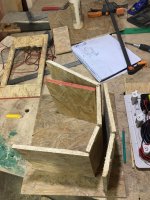
Second prototype assambled, i wish i was more sure about not being air leaks inside the box, but well, its a proto... The line was made a little shorter, port in front because at least the resonances are really well cancelled in this type of design, regardless of driver placement inside the high radius part (in sim). Measurements are lacking for now... But i got pics!


Finally made the measurements at the Uni from the second proto (my mic seems to have damaged and works only now and then). This one was made using an earthworks mic, calibration was done using a svantek meter yet seems that the values were lost due to exporting. We were in a rush so not many measurements averaged, just one...
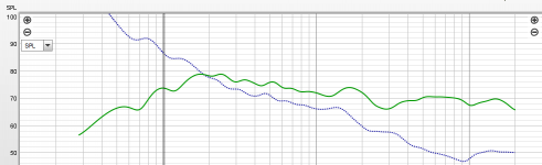
And the response is.....
AWFULL!

I'm not entirely sure if its a phase cancellation resulting in the port being upfront or a little "air" between driver gasket and front baffle, but it isn´t normal for sure, being that the line is approx the same as the other in the other measurement, but displayed differently. Any ideas or experiences?
*What i learned from the measurements in the lab:
The thielle small parameters i had were pretty on spot. We measured the Rlim and a Rtest with an LCR meter and adjusted the values in the software until everything matched. The speaker was hung from the roof to avoid reflections from the rear wave back into the cone, i guess gravity may matter (a real little) if u measuring a 18 incher. Still, all the values were pretty much the same as those i obtained cheap and dirty at home (electrical and mechanical).
What i did wrong at home was the VAS measurment. Added mass method seems to be more reliable as the actual volume of a box is hard to determine (with the speaker mounted). I used different things to add mass, but it was never really fixed to the cone. Also, the mass wasn't equally distributed around the cone. Luckily the professor instructed us to use modelling clay, making a ring of the size of the dustcap, and press a little until its perferctly glued (dont worry, if its not the tones will sound distorted as hell). I already suspected my VAS measurment was wrong because when i changed it in the simulation the response seemed more like the first measurment (were the line seemed to be working at expected Fs, yet it was low in level).
CONCLUSIONS: Just in case, i will stay away of front oriented ports... A (hopefully) definitive box is now to be assembled. If my mic wants, i may even be able to upload another response.
Best regards!
And the response is.....
AWFULL!
I'm not entirely sure if its a phase cancellation resulting in the port being upfront or a little "air" between driver gasket and front baffle, but it isn´t normal for sure, being that the line is approx the same as the other in the other measurement, but displayed differently. Any ideas or experiences?
*What i learned from the measurements in the lab:
The thielle small parameters i had were pretty on spot. We measured the Rlim and a Rtest with an LCR meter and adjusted the values in the software until everything matched. The speaker was hung from the roof to avoid reflections from the rear wave back into the cone, i guess gravity may matter (a real little) if u measuring a 18 incher. Still, all the values were pretty much the same as those i obtained cheap and dirty at home (electrical and mechanical).
What i did wrong at home was the VAS measurment. Added mass method seems to be more reliable as the actual volume of a box is hard to determine (with the speaker mounted). I used different things to add mass, but it was never really fixed to the cone. Also, the mass wasn't equally distributed around the cone. Luckily the professor instructed us to use modelling clay, making a ring of the size of the dustcap, and press a little until its perferctly glued (dont worry, if its not the tones will sound distorted as hell). I already suspected my VAS measurment was wrong because when i changed it in the simulation the response seemed more like the first measurment (were the line seemed to be working at expected Fs, yet it was low in level).
CONCLUSIONS: Just in case, i will stay away of front oriented ports... A (hopefully) definitive box is now to be assembled. If my mic wants, i may even be able to upload another response.
Best regards!
Indeed! Re leaks and long forum thread deleted 'in toto', my initial assertion that even the (cumulative) incredibly tiny leaks between the threads of threaded metal inserts/matching machine screws is enough in some vented alignments to generate the kind of performance measured here, so not seeing any continuous glue 'walls' around the panel joints certainly implies a potentially cumulatively massive leak, ditto driver install (not shown).
.......and what's with this port near driver being an issue? The original patent included a driver in vent, which at least Altec successfully used and FWIW/YMMV, me too, not mention the vast majority of BRs since then have by far had vents acoustically close to the woofer.
.......and what's with this port near driver being an issue? The original patent included a driver in vent, which at least Altec successfully used and FWIW/YMMV, me too, not mention the vast majority of BRs since then have by far had vents acoustically close to the woofer.
Ok then the protos, especially the second one is really misleading because of al the potential air leaks. I can tell you that u are right, construction of them wasn't the best in that regard, we used tones of silicon, yet many spots were hard to reach. Thanks!
Also, nice to know that the port upfront aint't bad as it's read every now and then.
With the new parameters i guess it will be a proper assembled box, port location subject to the driver's owner (a friend of mine). And a new measurment may shred some light as to how the sim correlates with the "reality" i can achieve trying a little harder. I think this will be the one, i guess i can make a little removable plate in the end of the line to make it alittle shorter and with a little bigger area to see what gives the better bass response in room.
Best regards!
- Home
- Loudspeakers
- Full Range
- Another FR attemp