Hi all!
After couple of years of reading this forum (a lot), I finally got to design my first chipamp PCB.
I'm a total amateur, surely there are errors in my design, but where should I go, if not here? 😉
I'm using LM4766, because:
1) is was available, while 3886 was not,
2) I don't need much power for starters,
3) I couldn't find any sensible 4766 pcb, so I thought that maybe I'll give it a shot.
I'm worried about a couple of things:
1) grounding (what else, really? 😀 )
2) overall layout or schematic bugs,
3) ...maybe crosstalk issues? Wrong feedback coupling?
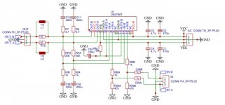
The design is based on the TI reference design, but I have used a lot of information from Circuitbasics, Neurochrome... I looked everywhere basically.
As I mentioned before, I'm an amateur - though I understand electricity and basic physics, I lack proper PhD Master Blaster Engineering educaton.
Thanks in advance, you all are awesome and I hope I'll learn some of electronics engineering myself, as much as it is possible for a hobbyist.
What do you think?
After couple of years of reading this forum (a lot), I finally got to design my first chipamp PCB.
I'm a total amateur, surely there are errors in my design, but where should I go, if not here? 😉
I'm using LM4766, because:
1) is was available, while 3886 was not,
2) I don't need much power for starters,
3) I couldn't find any sensible 4766 pcb, so I thought that maybe I'll give it a shot.
I'm worried about a couple of things:
1) grounding (what else, really? 😀 )
2) overall layout or schematic bugs,
3) ...maybe crosstalk issues? Wrong feedback coupling?
The design is based on the TI reference design, but I have used a lot of information from Circuitbasics, Neurochrome... I looked everywhere basically.
As I mentioned before, I'm an amateur - though I understand electricity and basic physics, I lack proper PhD Master Blaster Engineering educaton.
Thanks in advance, you all are awesome and I hope I'll learn some of electronics engineering myself, as much as it is possible for a hobbyist.
What do you think?
Attachments

Giving this thread a bump as I am wanting to use this chip, LM3886 are out of stock everywhere and this seems a good alternative to get me going.
1/ Use star grounding.
2/ Make sure feedback resistor path is as short as possible or you might get instability.
2/ Make sure feedback resistor path is as short as possible or you might get instability.
H
HAYK
I advise you to use Pavel Dudek way feedback network.
https://www.diyaudio.com/community/threads/why-not-pavel-dudeks-feedback-network.400403/
You need small 2.2uF 63v polypropylene capacitors for the input and the feedback with 220k resistors for grounding the inputs and DC feedback.
The input ground get it from a virtual ground by 2x10k resistors from each rail and bypass to ground with high voltage security 100nF with two rectifier diodes in parallel and tail-head.
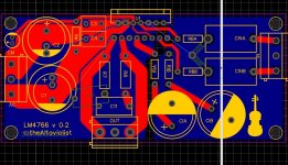
If you scoot R7 closer to R8 You can fit C10 on the top of the board.
What goes on in the input circuit? It seems like you have two resistors on the bottom of the board that are supposed to share (enormous) mounting holes with the two input caps. That's not a recipe for anything good. You can split the two input caps apart. C1A can go all the way to the board edge. That'll give you enough room for the resistors between the caps.
Just as in the LM3886 the ground pin on the LM4766 is only used during mute. So you only need to treat it carefully if you care tremendously about the sound quality when the chip is muted. 😉 Have a look here: https://neurochrome.com/pages/grounding
Tom
- Home
- Amplifiers
- Chip Amps
- LM4766 done left - first PCB design