Here's an easy circuit that will make a good first project for beginners or anyone looking to quickly build a phonostage with good performance and easy to find parts.
This is a variant of a commercial design I did recently, simplified a little to serve as an example of how to use a DC switching supply properly on another forum.
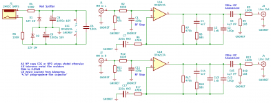
At it's heart it uses the OPA2134 op-amp. This JFET input device is easy to obtain and well regarded, although the input noise isn't quite as low as we might ideally want it to be. Having said that the circuit performance a lot better than 98% of circuits you can find out there on the web. The JFET input draws almost zero bias current so there's no need for input decoupling which considerably simplifies the design.
The circuit is designed to work off of an external 24V double-insulated SMPS which can be easily obtained from multiple outlets. The rails are split into +-12V using resistors R4 and R5 in conjunction with zener diodes D1 and D2. Doing this means we don't have to worry about using bias networks and the grief and fiddliness they bring along. C8 and C9 provide additional smoothing and AC decoupling to improve the efficiency of the supply when under load with audio frequency supply currents from the opamp. C6 (X7R type, all the rest are NP0/C0G) should be connected as close to the op-amp as possible to prevent HF instability.
Starting from the input, resistor R1 provides the 47k load for the cartridge and capacitor C1 does double duty acting as the 100pF capacitive load from the pre-amp and also as an RF stop in conjunction to series resistor R2. These should be connected as close to the input connectors as possible with the shortest possible wiring to assure maximum possible attenuation of RFI.
The RIAA equalisation network shown is active and ensures excellent headroom compared to a lossy passive network. If you use 1% metal film resistors and hand select Cs 4, 14, 3, 13 to within 2% of the specified value you will get RIAA accuracy to 0.25dB which is considerably better than most commercial offerings! Capacitor C7 ensures the DC gain is unity as any op-amp offsets will be amplified by 60dB, either pushing the output up against the rail or seriously degrading available headroom.
In conjunction with R9, C5 applies the 20Hz IEC amendment and also DC decouples the output. This applies 7dB of cut at 10Hz where subsonic disturbances are likely to be, reducing intermodulation distortion further down the signal path. Valve amps really hate this. C5 should be a film capacitor and is easily obtained from sites such as Aliexpress for a low cost.
Finally resistor R3 provides enough isolation from the line at HF to keep the opamp stable and sets the output impedance to a respectable round 100 ohms.
So there it is, 4 different ceramic capacitor values, 6 different resistor values, 2 different electrolytic capacitor values and pretty decent performance. Quite elegant if I say so myself!
EDIT: C6 should be X7R dielectric (it's what the 'unless stated' refers to)
This is a variant of a commercial design I did recently, simplified a little to serve as an example of how to use a DC switching supply properly on another forum.
At it's heart it uses the OPA2134 op-amp. This JFET input device is easy to obtain and well regarded, although the input noise isn't quite as low as we might ideally want it to be. Having said that the circuit performance a lot better than 98% of circuits you can find out there on the web. The JFET input draws almost zero bias current so there's no need for input decoupling which considerably simplifies the design.
The circuit is designed to work off of an external 24V double-insulated SMPS which can be easily obtained from multiple outlets. The rails are split into +-12V using resistors R4 and R5 in conjunction with zener diodes D1 and D2. Doing this means we don't have to worry about using bias networks and the grief and fiddliness they bring along. C8 and C9 provide additional smoothing and AC decoupling to improve the efficiency of the supply when under load with audio frequency supply currents from the opamp. C6 (X7R type, all the rest are NP0/C0G) should be connected as close to the op-amp as possible to prevent HF instability.
Starting from the input, resistor R1 provides the 47k load for the cartridge and capacitor C1 does double duty acting as the 100pF capacitive load from the pre-amp and also as an RF stop in conjunction to series resistor R2. These should be connected as close to the input connectors as possible with the shortest possible wiring to assure maximum possible attenuation of RFI.
The RIAA equalisation network shown is active and ensures excellent headroom compared to a lossy passive network. If you use 1% metal film resistors and hand select Cs 4, 14, 3, 13 to within 2% of the specified value you will get RIAA accuracy to 0.25dB which is considerably better than most commercial offerings! Capacitor C7 ensures the DC gain is unity as any op-amp offsets will be amplified by 60dB, either pushing the output up against the rail or seriously degrading available headroom.
In conjunction with R9, C5 applies the 20Hz IEC amendment and also DC decouples the output. This applies 7dB of cut at 10Hz where subsonic disturbances are likely to be, reducing intermodulation distortion further down the signal path. Valve amps really hate this. C5 should be a film capacitor and is easily obtained from sites such as Aliexpress for a low cost.
Finally resistor R3 provides enough isolation from the line at HF to keep the opamp stable and sets the output impedance to a respectable round 100 ohms.
So there it is, 4 different ceramic capacitor values, 6 different resistor values, 2 different electrolytic capacitor values and pretty decent performance. Quite elegant if I say so myself!
- 7 VRMS output 50Hz to 20kHz into a 10k load
- 40dB gain at 1kHz
- THD < 0.002% 20Hz to 20kHz
- SNR 75dB ref 5mV cartridge connected
- RIAA accuracy 0.25dB (ref IEC amendment) 50Hz to 20kHz
- Power consumption 200mW (no signal)
EDIT: C6 should be X7R dielectric (it's what the 'unless stated' refers to)
Attachments
Last edited:

Nice! I could see that being a handy way to whip up a phono preamp for a small system.
I have a question, though...
Would there be any downside (other than physical size) to substituting small polypropylene capacitors for the NP0/C0G caps you specify? I have this superstitious prejudice against ceramic dielectric...
Also, can overall gain be raised to perhaps 45dB by adjusting the value of R17 downward? Or would that upset the equalization?
Thanks for your kind comments. I would keep the 100pF caps C0G as they need good RF performance to ensure good rejection of EMI.Nice! I could see that being a handy way to whip up a phono preamp for a small system.
I have a question, though...
Would there be any downside (other than physical size) to substituting small polypropylene capacitors for the NP0/C0G caps you specify? I have this superstitious prejudice against ceramic dielectric...
You can most certainly use polypropylene for the 1n5 and 4n7 caps. I'm working on a commercial design for my own company that's only slightly more complicated than this circuit that uses 100V green classic polyester film caps without an appreciable increase in distortion. These really are extremely cheap and make hand selection for excellent RIAA accuracy very economical. 63V polyester kicks the distortion up a bit though. Polypropylene is an excellent choice if you can get it in these values. In my experience it's hard work finding readily available polypropylene caps under 10nF with a good degree of accuracy.
Your suspicions are quite justified regarding ceramic caps. X7R is horribly nonlinear but great for supply decoupling as the voltage stays constant. I've had superb results with TDK C0G through-hole caps. Just as linear as polypropylene and polystyrene film.
Adjusting R17 downward will affect the equalisation accuracy pulling the response down at HF I'm afraid.Also, can overall gain be raised to perhaps 45dB by adjusting the value of R17 downward? Or would that upset the equalization?
In any case, I would not recommend a gain of more than 40dB at 1kHz on 12V split rails as you'll have less than 20dB overload margin ref 5mV.
The values shown are quite a miraculous occurrence with standard component values, it's highly unlikely you'll be able to do better after changing the gain, resulting in considerable complexity.
40dB is enough for a pretty decent level. I don't recommend the OPA2134 for high output MC if that's where you're going?
Thanks for the clarifications.
Re: gain:
Understood about R17. No messing with that value.
I've found that to get records to play at roughly the same subjective level as digital sources, a bit more than 40dB is required from the phono stage with the MM cartridges I use. It's not a big deal, though. 40dB is perfectly adequate, and all it takes is a couple of upward clicks on the volume knob to bring playback level to parity with the output from the DAC.
When I'm on +-15V or greater rails I go for 41-43dB, but having seen the transient output of a moving magnet cart on a clicky disc I'm inclined to want to preserve overload margin over subjective loudness.I've found that to get records to play at roughly the same subjective level as digital sources, a bit more than 40dB is required from the phono stage with the MM cartridges I use. It's not a big deal, though. 40dB is perfectly adequate, and all it takes is a couple of upward clicks on the volume knob to bring playback level to parity with the output from the DAC.
Maybe listening to classical music makes me less inclined to want to bring the level up as digital sources from this genre tend to want to preserve dynamic range over maximum continuous level. The loudness wars strike again...
Ah, that does make sense. I listen to classical music too, but most often it's jazz or Latin popular music. I go on benders where I listen to nothing but Bach or Mahler or some other composer I get obsessed with for a while. But my volume control stays at about the same place. I think that's because I don't listen to any contemporary pop music that tends to be literally smashed with digital limiting/dynamics compression. For those rare times I listen to something like Radiohead or some contemporary R&B, the volume control comes down a couple of ticks.
Perhaps I should set my DAC to its 1V rms 0dBFS output level setting (it has that), and be happy with lower gain from the phono preamp. ; )
Perhaps I should set my DAC to its 1V rms 0dBFS output level setting (it has that), and be happy with lower gain from the phono preamp. ; )
Last edited:
Even if Ebay is full with OPA2134 they are all fake chinese fake components. Where can you real OPA2134 in Europe?
And one more. Which kind of audiphile capacitor is recommended for decoupling an phono MM pre output. Voltage around 50V?
Wima MKS, Kemet ?
Wima MKS, Kemet ?
Thanks for sharing @monty78pig this simple and cool design ! 😎 😎 😎
I have a question : is your circuit following the RIAA extension to 20Hz ?
T
I have a question : is your circuit following the RIAA extension to 20Hz ?
T
@monty78pig - is it your intention that the power supply will deliver zener-regulated rails of +/-12V? The zeners will not conduct with the circuit as shown. The SMPS needs to deliver more than 24V.
- Home
- Source & Line
- Analogue Source
- Super easy phonostage using OPA2134 and 24V wall-wart