I built the ACA Mini almost clone (many thanks to Papa and Kevin for that). It is a truly great sounding little amp. I love it. So I wanted to go a step further and make the same thing in a proper chassis that I could give to my daughters.
FWIW I laid out my own version of Mini ACA. And I sent out for boards and got them back. I felt I could do better so re-did it and also added a TL071 unity gain inverter to feed a bridged mono-block arrangement.
Does anyone out there want to cooperate on this, i.e. check the schematic and layout and provide suggestions or blessings? I'll probably get 10 boards made (again) so would share pairs at cost. BTW, these are mono boards with JST connectors (or soldered wires could be used) designed to go in a chassis and use conventional heat sinks. Is anyone interested in helping with an engineering review to be sure these turn out as they should? Let me know. I'd like to order the next round of boards soon. Thanks. BTW, I'd be happy to share the schematic and layout for review. Please PM me if interested.
Last edited:
This is what the single channel Almost 1/2 Clone mono board looks like next to an Almost Clone Stereo board. Again, if anyone could help review the design before I go out for the next rev I'd appreciate it. Thanks!

Hi
A few suggestions;
1. I would move P1 and P2 closer to the output MOSFET.
2. Not sure you need the 2 mounting holes near the MOSFET. You could leave the mounting holes there and move your MOSFET closer to each other. If you can try to follow a UMS pattern.
3. I would add some extra pads and move 1-2 components near C1 so a better quality input cap could be used.
4. I normally add a nice polypropylene cap (about 2uF) across the big output cap.
Very nice work!
That’s it..😃
BR
Eric
Last edited:

Thanks Eric! I'll have a look at those things.Hi
A few suggestions;
1. I would move P1 and P2 closer to the output MOSFET.
2. Not sure you need the 2 mounting holes near the MOSFET. You could leave the mounting holes there and move your MOSFET closer to each other. If you can try to follow a UMS pattern.
3. I would add some extra pads and move 1-2 components near C1 so a better quality input cap could be used.
4. I normally add a nice polypropylene cap (about 2uF) across the big output cap.
Very nice work!
That’s it..😃
BR
Eric
By getting rid of the mounting holes I assume you mean use the MOSFETs bolted to the heatsinks as the mounts on that side of the board.?
Also, the new version is not a big board. Layout attached. 4500 mils (4.5") wide. I don't think I should move the MOSFETs any closer together so they are well placed to dissipate heat on a single heat sink about 150~200 mm long. If you think otherwise please let me know why that would be. I'm not well versed in these things. Thanks again.
Last edited:
Yep, that’s what I meant with the mounting holes. I haven’t verified the layout but adding the option to create a bridge mono configuration via the inverter is a great idea.
Nobody can verify your layout vs schematic, I believe you didn’t share your schematic yet.
BR
Eric
Nobody can verify your layout vs schematic, I believe you didn’t share your schematic yet.
BR
Eric
Hi Eric,Yep, that’s what I meant with the mounting holes. I haven’t verified the layout but adding the option to create a bridge mono configuration via the inverter is a great idea.
Nobody can verify your layout vs schematic, I believe you didn’t share your schematic yet.
BR
Eric
Thanks for looking at this. BTW, I did change the trim pots to be much closer to the output MOSFETS.
And I'll have a look at UMS compliance next.
I entered the schematic in KiCAD. That program is marvelous!
Here is the schematic with a few notes and questions:
- The main channel is the same as Papa's. The super cap circuit may have the parts ordered differently .
- I would not populate and use that anyway, I prefer the "without jumper" sound
- The new stuff is the inverter where all such part numbers have a 2x number.
- If it won't be used anything with a 2x PN can be omitted.
- The inverter circuit has jumpers for power and signal so can be populated yet left fully 'off' if desired.
- The I/O and power connectors are JST plug ins, not the type used in the original.
- End use level connectors would be on the chassis, not the board.
- The inverter is a TL071, so should be unity gain stable and hence no compensation is used.
- Also no bypass cap is on the op amp PS as it it's for a low frequency (i.e. audio) signal and already has its own 1k filter cap nearby.
- I also added a resistor (470 ohm) to the filter and think I could have gone higher than 470 on that. Thoughts?
- And did I even need a separate filter or I could I have tapped into the bias supply? Thoughts?
- Considering the idle current of the TL071 plus signal load in actual use, I'm not sure this would draw more than 10 mA at most. Thoughts?
- After all, it's all low line level signal into a fairly hi Z load.
that's mini F5, not Mini ACA
catch is in my brain ........ difference between Mini ACA and ACA Mini

ZM Omniconfused
catch is in my brain ........ difference between Mini ACA and ACA Mini
ZM Omniconfused
Sorry, I'm not sure what I did but it's definitely an ACA Mini (Mini ACA?) - with a twistthat's mini F5, not Mini ACA
catch is in my brain ........ difference between Mini ACA and ACA Mini
ZM Omniconfused
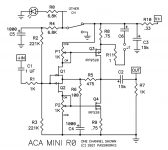
Indeed. I copied it to be implemented as mono boards with line inverter added so one could feed the other in bridged mode. I know enough about this stuff to be dangerous but not enough to be an expert. I'm just looking for feedback on the layout and inverter from people that know more than me. Opinions and guidance are appreciated. Thanks.Nelson Pass named the ACA Mini and drew its schematic this way:
_
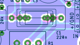
It’s unfortunate that C1 physical size is still very small, by moving OFFS+ on the left side and moving 2 small lines toward the top of the PCB would allow you to fit better quality cap.
For C1 you could do something similar to this pic which allows you a few different cap size.
On your silkscreen for J2 why write C. Isn’t this the standby switch.
Thanks
Eric
For C1 you could do something similar to this pic which allows you a few different cap size.
On your silkscreen for J2 why write C. Isn’t this the standby switch.
Thanks
Eric
Attachments
Hi Eric,It’s unfortunate that C1 physical size is still very small, by moving OFFS+ on the left side and moving 2 small lines toward the top of the PCB would allow you to fit better quality cap.
For C1 you could do something similar to this pic which allows you a few different cap size.
On your silkscreen for J2 why write C. Isn’t this the standby switch.
Thanks
Eric
Thanks for the feedback. Much appreciated.
The - C + is labeled as such so you know which wire goes where on the standby switch.
C = common or center pole on the switch. -/+ are self explanatory.
Is there a better standard for the center pole that I should use?
I'll have a look at the cap issue.
But I've built the ACA clone and used the specified cap and I really like the sound,. Will a different type of cap give me a noticeable better sound??
What cap would you recommend instead of the normally specified cap?
Thanks!
Sizing the lead spacing for the correct value in Silmic II at the correct voltage (or the next voltage rating up) isn't the worst idea. I never checked to see what was spec'd. I just know this was an issue on the Korg Nutube board and the Stasis front end for the DC blockers.
I think that e_fortier is suggesting the spacing be appropriate for film caps. Probably not the worst idea. The BA-3 front end has an interesting setup for the DC blocker 10uf cap. A spot for a either a small electrolytic or a rather large film. Both of which are paralleled so you can choose either.
With the reputation that this little amp has, you may see a difference in using nice PPP caps. I tried Clarity Caps PS CSA, some stealth caps, electrolytics etc. in some other designs. All presented a slightly different sound and range of detail. The clarity caps presented a good value and I believe they are used in some pass gear.
Yeah, those caps at 25V are close to the line. But should never go over with the well regulated SMPS in use. And I'll have a look at using a different input coupling cap, if possible. BTW, check your messages.Sizing the lead spacing for the correct value in Silmic II at the correct voltage (or the next voltage rating up) isn't the worst idea. I never checked to see what was spec'd. I just know this was an issue on the Korg Nutube board and the Stasis front end for the DC blockers.
I think that e_fortier is suggesting the spacing be appropriate for film caps. Probably not the worst idea. The BA-3 front end has an interesting setup for the DC blocker 10uf cap. A spot for a either a small electrolytic or a rather large film. Both of which are paralleled so you can choose either.
With the reputation that this little amp has, you may see a difference in using nice PPP caps. I tried Clarity Caps PS CSA, some stealth caps, electrolytics etc. in some other designs. All presented a slightly different sound and range of detail. The clarity caps presented a good value and I believe they are used in some pass gear.
BTW, BTW, if you look at the input impedance and do the math , you will see that a 1 uF cap is much more than adequate to allow even subsonic frequencies.
Anything more than 1uF is unneeded overkill. But quality is a different issue and I will check out the clarity caps. Yet so far I'm not convinced that something different is necessary. But I'll look into it. but please make a case for an audible difference if there is one. What would I expect above the currently spec'd film caps?
Anything more than 1uF is unneeded overkill. But quality is a different issue and I will check out the clarity caps. Yet so far I'm not convinced that something different is necessary. But I'll look into it. but please make a case for an audible difference if there is one. What would I expect above the currently spec'd film caps?
Hi
I don’t want to start a debate about input cap. The one supplied sounds good and is Metallized Polyester. Diyer tend to want to try input cap because it influences the overall sound.
When I mentioned that the cap C1 is small I mean the physical size not the 1uF value.
Buy a nice fancy cap rated 1uF, 400V and it won’t fit on your PCB. Not that it needs too, these are your pcb. Wish I had your knowledge to design pcb, whenever I need a small design I normally contact Prasi, he’s got very good design fees.
The above are just suggestions, you don’t have to modify anything.
You had good suggestions! I have moved the trim pots closer to the MOSFETS and have also realigned them and the mounting holes to be UMS compliant although they may still need movement but not different spacing. And I have shortened the input path. All good stuff!! So many thanks!Hi
I don’t want to start a debate about input cap. The one supplied sounds good and is Metallized Polyester. Diyer tend to want to try input cap because it influences the overall sound.
When I mentioned that the cap C1 is small I mean the physical size not the 1uF value.
Buy a nice fancy cap rated 1uF, 400V and it won’t fit on your PCB. Not that it needs too, these are your pcb. Wish I had your knowledge to design pcb, whenever I need a small design I normally contact Prasi, he’s got very good design fees.
The above are just suggestions, you don’t have to modify anything.
I'll see what will fit on board but I'm guessing a big cap may not cooperate with the needed board space. But I'll fid out when I start playing with it. Either way, I'm gonna generate all the files and have these boards built in the next day or two with whatever will fit.
The small radial Metallized Polyester caps aren't bad. There are a lot of nice caps under $10 each. Clarity caps being one.
For instance:
https://www.madisoundspeakerstore.com/px-cap-250vdc/claritycap-1.0-mfd-px-range-polypropylene-caps/
I wasn't much of a believer in boutique caps until I did A/B testing on a Korg Nutube B1 preamp that I have (I have two). If this little mini is detailed (I believe I read somewhere that it is) then you might hear these differences a bit easier. With the Korg, pretty much everything improved. I try not spend more than $10 on a signal path cap. $10 is a good compromise to milk a little extra out of the amp without going too crazy.
With the size of the C1 being 1uf, that makes for a lot of physically small options. Also, just making the holes large enough to handle the leads on these boutique caps would make things good enough for someone to macgyver them in there if they wanted to.
Hi Mike, Reviving this. Is a 1 mm hole big enough for the nice caps you speak of?
I will check when I get home later today. I believe I have some PX caps sitting in a drawer. I should also have some CSA
- Home
- Amplifiers
- Pass Labs
- DIY ACA Mini twist - help?