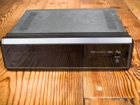
I have this old TDA1541A-based DAC lying around and hope someone is able to share its schematic. Here are some pictures.
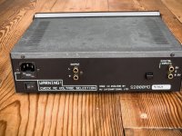
And can anyone explain why there are two inputs, marked 5V and 1/5V?
And can anyone explain why there are two inputs, marked 5V and 1/5V?
Attachments
Now everyone, take it easy, not all at the same time…
(bump)
Surely this is a bit of a needle in a haystack, but who knows.
(bump)
Surely this is a bit of a needle in a haystack, but who knows.
5v and .2v to handle SPDIf and the 3 pin balanced connector input I cannot remember the name of 🙂
no ccts available as far as I am aware, but should sound nice 🙂
no ccts available as far as I am aware, but should sound nice 🙂
S/PDIF standard voltage is relatively low at around 0.2V, with a maximum of about 0.6V
Some motherboards output S/PDIF at very high TTL Logic levels, which can go as high as 5V
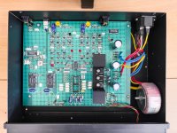
You could use any TDA1541 with Philips "SAA chipset" schematics - that particular DAC differs in a way that it has a transistor output stage.
Some motherboards output S/PDIF at very high TTL Logic levels, which can go as high as 5V
You could use any TDA1541 with Philips "SAA chipset" schematics - that particular DAC differs in a way that it has a transistor output stage.