If you're here, you're probably searching for info on the Toshiba TA7136 (aka the TA7136P or TA7136AP) op amp. You may be having trouble with a device that uses it. Let me guess: is it picking up FM radio? Does it sound a bit fuzzy? Is the noise floor strangely elevated?
You may be having stability issues. This was the case with the Onkyo A-5 I revamped.
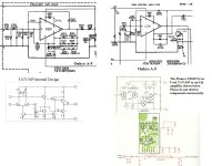
Using the spice model of the TA7136 that I developed for the Onkyo, here's the simulated loopgain plot of the tone control reference circuit suggested by the TA7136 datasheet. It's really bad: simulated phase margin and gain margin are zero, as the loopgain phase crosses through -180 degrees right at the ULGF around 1.6MHz.
It's possible to design a circuit around the TA7136 with generous stability margins, and retain plenty of in-band feedback; Toshiba just didn't bother. It's yet another example of bad datasheet reference circuits informing bad mass-produced applications.
You may be having stability issues. This was the case with the Onkyo A-5 I revamped.
Using the spice model of the TA7136 that I developed for the Onkyo, here's the simulated loopgain plot of the tone control reference circuit suggested by the TA7136 datasheet. It's really bad: simulated phase margin and gain margin are zero, as the loopgain phase crosses through -180 degrees right at the ULGF around 1.6MHz.
It's possible to design a circuit around the TA7136 with generous stability margins, and retain plenty of in-band feedback; Toshiba just didn't bother. It's yet another example of bad datasheet reference circuits informing bad mass-produced applications.
Attachments

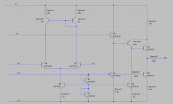
For reference, here's the TA7136 model I used.
The resistor values are guesses, since the datasheet omits them. The critical "Rguess6" value of 270 ohms was verified experimentally (by drawing current from P6 and observing the change in voltage at P1.) That resistor's value affects the circuit's stability more than any other.
The resistor values are guesses, since the datasheet omits them. The critical "Rguess6" value of 270 ohms was verified experimentally (by drawing current from P6 and observing the change in voltage at P1.) That resistor's value affects the circuit's stability more than any other.
Revising the TA7136 model
Why is the reference circuit's stability so bad? Is the simulation in post #1 really right?
Maybe not: with a 100k resistor driving pin 5, the current sources at Q11 and Q3 only conduct tens of microamps. That can't be right, that's not enough.
Let's fix this. On the original datasheet, the two diodes are named Q1 and Q2. Not D1 and D2. That's a hint: they may be diode-connected transistors, with Vbe matched to Q3 and Q11. That would make sense.
Indeed, the model works better if we substitute diode-connected BJTs and revise the values of Rguess3 and Rguess5 a bit. Now, the current sources act much more like normal current mirrors -- Q3 and Q11 will supply current that's reliably within a factor of two of that supplied to pin 5, over a wide range. I bet that's what's on the chip.
Guess what: the reference circuit's stability is even worse with this change. It is a basket case.
Here's the revised TA7136 model. To prove that this opamp isn't 100% awful, here's a revised tone control "reference circuit" with generous stability margins and generous in-band loopgain. This is what the datasheet should have said.
Attachments


I am extending on Lamp Cord Labs:
..
1980~1990 owned and operated a service center just out side of Pittsburgh PA before the steel industry funeral. Having been Yamaha "Preferred Service Center". I was also authorized service center for ONKYO (later employee as technical supervisor), Denon, Sanyo, Fisher, Kenwood, Pioneer, NAD, Luxman, GAS, etc in all 23 US, EURO, and Japanese products represented.
..
TA7136P and TA7136AP while similar by design, Toshiba email communication seems to suggest that the TA7136P has low noise (S/N) as compared to TA7136AP. One thing is for sure. Not all engineers utilize components as they should. As a PHONO EQ circuit the IC should be designed with capacities feedback which A5 has incorporated than using resistors+capacitors. The IC is very sensitive to noise if the power supply egulator is not clean; has harmonics of its own. I believe the A5 uses a +- 17VDc with the positive being lower by 0.500VDc.
...
Many companies have used this part for various application such as sensor amplification. During the mid 1980's these IC's did show a fairly good RIAA response curve using test tone vinyl recordings and spectrum analyzer. I also recall that the spectral curve response differed slightly based on the fact that the ICs themselves will have some spec deviation for the same reason discrete transistors will have differences in gain. By no means these devices are as good as a discrete circuit utilizing FET transistors which Onkyo Yamaha Denon NAD etc have used in some models EQ circuit.
They are not bad at all in performance assuming they are properly configured to a good matching head shell (pickup). In addition any electrolytic capacitor around the IC should be checked and by all means keep the cap voltage and capacitance similar to the design. Don't use higher voltage caps than recomended.
One of the mistakes would be to expect identical L+R channel outouts. That just does not happen. There is always a difference.
...
In Tone control circuit what is presented by JCP2001 is workable and is very good.
..
1980~1990 owned and operated a service center just out side of Pittsburgh PA before the steel industry funeral. Having been Yamaha "Preferred Service Center". I was also authorized service center for ONKYO (later employee as technical supervisor), Denon, Sanyo, Fisher, Kenwood, Pioneer, NAD, Luxman, GAS, etc in all 23 US, EURO, and Japanese products represented.
..
TA7136P and TA7136AP while similar by design, Toshiba email communication seems to suggest that the TA7136P has low noise (S/N) as compared to TA7136AP. One thing is for sure. Not all engineers utilize components as they should. As a PHONO EQ circuit the IC should be designed with capacities feedback which A5 has incorporated than using resistors+capacitors. The IC is very sensitive to noise if the power supply egulator is not clean; has harmonics of its own. I believe the A5 uses a +- 17VDc with the positive being lower by 0.500VDc.
...
Many companies have used this part for various application such as sensor amplification. During the mid 1980's these IC's did show a fairly good RIAA response curve using test tone vinyl recordings and spectrum analyzer. I also recall that the spectral curve response differed slightly based on the fact that the ICs themselves will have some spec deviation for the same reason discrete transistors will have differences in gain. By no means these devices are as good as a discrete circuit utilizing FET transistors which Onkyo Yamaha Denon NAD etc have used in some models EQ circuit.
They are not bad at all in performance assuming they are properly configured to a good matching head shell (pickup). In addition any electrolytic capacitor around the IC should be checked and by all means keep the cap voltage and capacitance similar to the design. Don't use higher voltage caps than recomended.
One of the mistakes would be to expect identical L+R channel outouts. That just does not happen. There is always a difference.
...
In Tone control circuit what is presented by JCP2001 is workable and is very good.