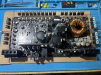
Just got an RF P1000x2 in on a trade, 1 output FET blown on each high/low side, removed all output FETs, Powers on blue light only/not in protect (red/left LED on while rail charges then goes off) I get power supply switching up to Rectifiers, no switching on any of the output Gates (which is the low side FETs between the 2 groups? IRF6218 and IRF3415 are what’s used, 4 each per side per channel)
While on it seems to idle normal at about 1.8a but then climbs by .10a until it gets to about 3.5a then protect kicks on, takes about 60 seconds from power up til protect kicks on. I also noticed negative rail will not discharge when power is turned off (I always check rail voltage constantly, habit now lol) I have to discharge it myself, positive rail discharges as it should.
I am not familiar with Fosgate amps so I installed new FETs, ran a 50hz signal @ 1vpkpk just to see what it did and it acts the same, comes on clean, switching up to rectifiers, idle current climbs but I notice output FETs are getting hot, way hotter then it should, I kill power soon as idle gets to about 2.8a because of how how FETs were getting.
Only difference of symptoms when FETs installed that I can tell is they heat up. Any help for a starting point with this amp would be GREATLY appreciated, just a few pics for reference included, unmarked FETs on left was the problem channel, replaced all 8 vs just the 1+1 that blew) the blowout was internal on those 2 as well, no Big Bang or magic smoke even that I can smell. I’m going to start probing everything everything with my multimeter, etc to see if I am randomly find any bad components in the meantime, always have good luck when I do and I learn some so 🤓
Thank you!
P.S. climbing idle has me weary of keeping it on for more then 30/45 seconds at a time, the one time i let it run until protect kicked on it wouldn’t power back up for a lil bit, I’m assuming it may be a heat issue, and I do not have a thermal imaging camera yet :/ (seeking a used thermal imaging unit if anyone has one for sale) 🖖🏼
Attachments
They are glued, I can remove the glue tho, I’ve never interacted with bias potentiometers before, I don’t even know what they do actually, I’m going to read up on them, adjust as advised and test, I’ll report back once I do, ty.
Looks like everything is switching correctly from what I can see, but nothing looks familiar to me 😅 I see my 50hz input signal frequency on each of the output tabs/drain. Idles at 1.2a with both bias pots turned full ccw, nothing is overheating and amp stays powered on/blue led only.
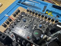
Is this Fosgate’s Class BD bespoke design? It looks like it has emitter resistors but these are SMPS MOSFETs? Just wow weird, my first RF (besides my Pumch800a2 project) so def a system shock to a newb tech after working on old school Korean class D designs for last few months.
Negative rail is not draining tho, positive drains, although seems to be much slower now that the bias pots have been turned down, but ya I have to manually drain the negative rail, each caps out at 50v. Is that normal? I’m about to attach a speaker to each output terminal to test for sound, just had to post this beforehand cuz wow, so different, looking forward to learning it 🙂
ty Perry 🖖🏼
pic is of the output FETs tab/drain
Attachments
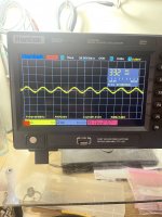
Output terminals each reproduce the input signal 🙂 all seems to be working great, except that weird idle current climb and negative rail not draining, any advice on either of those 2 would be awesome, and I have the bias pots marked to what their position was before turning full ccw, but haven’t touched them since turning them down.
Also I noticed 2 of the large Gate resistors that are 0.1 Ω are off by a lot
R86 measures 26 Ω
R93 measures 90 Ω
Going to pull each to see how they measure out of circuit
Also I noticed 2 of the large Gate resistors that are 0.1 Ω are off by a lot
R86 measures 26 Ω
R93 measures 90 Ω
Going to pull each to see how they measure out of circuit
Last edited:
The BD is a switching amp. This is a linear amp. They are completely different.
You need to adjust the bias (everything needs to be tightly clamped to the heatsink).
You need to adjust the bias (everything needs to be tightly clamped to the heatsink).
Ahh ok, ty for clearing that up. Just looks/acts so much different then what I am used to.
I am reassembling now, is there a specific guide online to adjusting the bias I should look up? I’ve just never done it, going to research it now while reassembling
I am reassembling now, is there a specific guide online to adjusting the bias I should look up? I’ve just never done it, going to research it now while reassembling
Ty Perry, I still haven’t gotten a video card but my tablet with that browser add on seems to work, I’ll try it out.
Also those resistors marked 0.1 Ω @ R86 and R93 are now out of circuit and measuring 2k and 20k. The sockets still measure 26 Ω and 90 Ω tho, going to check another out of circuit to compare. Should those empty sockets still measure what they are 26&90?
Also those resistors marked 0.1 Ω @ R86 and R93 are now out of circuit and measuring 2k and 20k. The sockets still measure 26 Ω and 90 Ω tho, going to check another out of circuit to compare. Should those empty sockets still measure what they are 26&90?
26 Ω is normal, compared to R15, which is same position just after the quad digit marked resistors, assuming the 90 at the end is the others in parallel 🙂 replacing the 2 bad ones with spares, thinking that may fix the negative rail not draining.
The pads won't likely read open due to protection circuit resistors being connected to them. Get the diagram from Rockford and post it if you need more definitive information.
Ya I figured it out 🙂 Is there any reason why negative rail isn’t draining with board out of chassis? Maybe assuming it’s because of that reason? Board not grounded to a chassis? Just never came across that situation where a rail didn’t automatically drain itself when positive does.
Thx again for everything Perry, hope you and yours are doing good 🖖🏼
Thx again for everything Perry, hope you and yours are doing good 🖖🏼
Some amps that don't have bleeder resistors have rail caps that remain charged for a long time. it's not really an issue.
After you get the bias set, that may change but I wouldn't think it's a problem.
After you get the bias set, that may change but I wouldn't think it's a problem.
- Home
- General Interest
- Car Audio
- Rockford Fosgate Punch P1000x2 - Blown Output FETs