Hey
I am looking to do some A/B testing with and without bypass capacitors to see if there are any meaningful changes in sound.
Is there any way I can do such a thing without having to solder and desorder?
Ideally, it would need to be as fast and hassle-free as possible because our auditory memory can only last so long. However, a high-quality connection is preferred to eliminate as much additional inductance or audible sonic degradation as possible.
Do you guys have some suggestions? I came across a forum post where someone did that, and he used copper alligator clips. https://www.distrelec.ch/de/krokodi...t5mrV2aO7a65SHZX9IJdRkZbe5zmM0-xoCWE4QAvD_BwE
I also considered these: https://www.ebay.com/itm/333324685360 and soldering the PCB mount part to the capacitors that I intended to bypass, but I think it would take longer to swap back and forth with this variant.
Any suggestions are welcome!
If it's for a quick testing the crocodile thingys are a good way to go but if you want to have a "by-ear" test means longer connection I would use the screw clamps. Is the placement of the cap for crossover or for amp usage?
Just buying alot of different "Audiograde" caps results in paying much for minor changes in the sound signature.
When you make switchable connections instead of a direct soldered connection you might not get the best results depending on the quality of the connection...
Maybe an already existing test may be enough for choosing and skipping the hussle of an endless loop of tests 😉
As you can read I prefer the more lazy method and use the fitting cap with the lowest esr and a well working cheap solution was always the good old red Wimas.

And here is the missing link to the already existing published test of caps:
https://www.humblehomemadehifi.com/Cap.html
https://www.humblehomemadehifi.com/Cap.html
Thank you. I know this test inside out. It was more for bypass capacitors in tube amp power supply. It is a common practice to put 0.1uF foil caps in parallel to the big electrolytics in the power supply and according to some renowned amplifier designers an aboslute must. But, some people in the forum did some measurements and the results say that bypass caps in the power supply do nothing and can even degrade sonics. So, I just wanna judge myself by ear.And here is the missing link to the already existing published test of caps:
https://www.humblehomemadehifi.com/Cap.html
Just a small explanation to why I want to the test, no need to have the debate (again) if it will yield positive results or not 🙂
I will probably use the Jantzen CrossCap for this test, they cost less than $1 each and have tight tollerances. If it does anything, I will upgrade to better ones.
Do you have some favorite caps?
Last edited:
Is there any way I can do such a thing without having to solder and desorder?

I stopped soldering-in/out my household lamps. I use switches.do such a thing without having to solder and desorder?
Also safer than handling high voltage.
Does this work for the pins of the electrolytic cap? It isn't a point-to-point wired amp but has a PCB
Last edited:
I got your test scenario wrong so for bypassing reasons the best test results are done in the final form. I would second the suggestion to solder the cap directly in place and just snipping one lead to see if there are any changes. If done well the connection could be re-soldered again without any issues. Guess in the end the quicker way with least possible influence from additional connectors.Best way is to solder the cap in, listen, then snip one lead with an insulated tool, while muting the speakers.
Only takes a moment. If you want to go back and forth, then at least one lead will need a connector.
However, long term listening is actually better.
I would use a 5-6 contact rotary switch allowing me to switch same amount of capacitors in a second.
You may mount it and capacitors in a small plastic box for insulation, where 2 short pigtails leave , either soldered to original board or with a couple crocodile clips.
Just be CERTAIN to mute amp/preamp before switching; as easy as grounding next grid with a pushbutton.
Just as a side note: I would throw a fistful of caps on a table and have a friend solder them to switch inside case, then put the cover on, while you are outside the room, of course not telling you which is which.
While testing, you rotate switch and compare capacitors identified only by "#1 - #2 ..... #6" with NO CLUE of which is which.
Write your audible impressions on a piece of paper and only after you get satisfied/sick of testing you turn amp off and open plastic case, to match audible results to actual caps.
Avoids expectation bias big time and makes results way more credible.
Then please post results here, if you wish.
Consider leaving all the capacitors connected through bleed resistors. Short the resistor associated with the capacitor under test to insert it into the circuit. Resistors on the order of a megohm will keep the capacitors at the right potential to reduce switching noise. The out of circuit capacitors will have no effect in a bypass application when connected through such large resistances. Added safety bonus is that they should all discharge when the unit is turned off.
Can you maybe link an example of such a switch?I would use a 5-6 contact rotary switch allowing me to switch same amount of capacitors in a second.
I am not sure how to do that, to be perfectly honest.Consider leaving all the capacitors connected through bleed resistors
JMFahey said:
I would use a 5-6 contact rotary switch allowing me to switch same amount of capacitors in a second.
Link: https://www.amazon.com/uxcell®-Rotary-Selector-Switch-Positions/dp/B0094DWSY0Can you maybe link an example of such a switch?

wiring:
Agree that´s the "normal" way but here we are trying to find minuscule sound differences, so any other component connected to capacitor in test must be avoided.
Bleed resistors will load gain stages, even 1M resistors can be significative (under these circumstances).
Too complicated with resistors.
This one is available in my country.
I still don't quite understand how you would wire it. If the bypass capacitor is soldered directly to the pins of the power supply cap.
This one is available in my country.
I still don't quite understand how you would wire it. If the bypass capacitor is soldered directly to the pins of the power supply cap.
Last edited:
How/where did you intend to solder that original bypass cap?
My schematic clearly shows two pins which are equivalent to a bypass capacitor.
Solder them where you would have soldered the original one.
Use 2 short pieces of wire and as I said, for safety try to mount this switch and all 6 capacitors inside a small plastic box.
Even a small Tupperware container can do, this is not a commercial product to be sold or a definitive installation which will stay there forever but just a test setup.
Once you found your favourite capacitor, IF there is any difference of course, then you solder it fixed where it belongs and keep the case + switch away for future comparisons.
Just curious which is "my Country"available in my country.
Switzerland, I thought I sent a link with a switch apparently I didn't. https://www.reichelt.com/ch/en/step...positions-ds-2-p7212.html?&trstct=pol_2&nbc=1
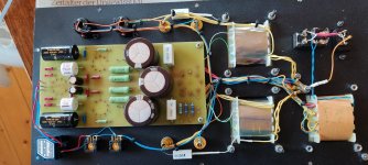
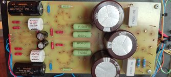
The caps I intend to bypass are the big red-brownish ones (220uF 400V) they are part of the power supply.
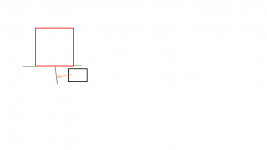
I obviously have to solder the bypass caps on the other side of the PCB. On the drawing the black square is the bypass caps, red PSU cap, green line is the PCB.
The caps I intend to bypass are the big red-brownish ones (220uF 400V) they are part of the power supply.
I obviously have to solder the bypass caps on the other side of the PCB. On the drawing the black square is the bypass caps, red PSU cap, green line is the PCB.
Attachments
Last edited:
- Home
- Design & Build
- Parts
- Best way to make a hot-swap connection for capacitors?