I just picked this up for next to nothing on FB Marketplace. Very cool piece!
I can't find any reference to this model anywhere, nor any pictures. It appears to be the "mack daddy" of the Magnus Electric Chord Organ line - it has every feature that I've ever seen on a Magnus; 37 key manual with switchable chorus, major and minor chord box, 8 bass tabs, voicing switches, tremolo, and a surprisingly beefy tube amp (push-pull EL84, with three 12AX7 for preamp, tremolo oscillator, and phase inverter, EZ81 rectifier) going into a comically-undersized 8" ceramic speaker. The transformers date to late 1961, so it's probably a 1962 model.
The acoustic portion works perfectly - quiet blower, no hung notes, no sticky keys, all chords and bass notes work. The amp needs some work, but hopefully it's something simple; the rectifier lights up, but none of the other heaters come on, so I suspect loose/broken heater wiring. Regardless, barring a blown transformer, I'm sure I can fix it.
Unfortunately the manual is about 20 cents sharp, and the bass tabs are a full quarter-tone sharp, but that's what Melodyne is for, right?
I'll add pictures later when I get a chance. In the meantime, is anyone else familiar with this model, or can anyone provide any other context? Thanks!
Sat down during a hockey game the other night (Let's Go Canes!) and traced out the schematic as best I can. There are some cap values that I'll need to confirm once I actually dig into it. The chassis contains several "modular" circuits (for lack of a better term) that have various umbilicals to the rest of the instrument - one shielded twisted pair for the pot on the expression pedal, two RCAs, and a four-pin cable (three signals and ground) that connects up to the main control panel. I don't know exactly what happens up there, but I'm hoping I won't have to - that once I replace failed/out-spec components, things will just work.
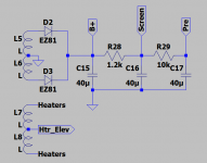
The power supply is ultra-traditional: cap input, with B+, screen, and preamp supplies. The heaters are elevated from the cathodes of the EL84 pair:

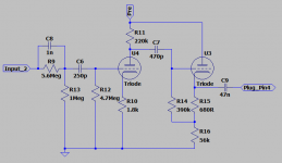
The RCA input that I've labeled as "Input_2" is a 12AX7 voltage amp and bootstrapped cathode follower. The input has an attenuating second-order high-pass filter that simulates at -3dB at 288Hz and -6dB at 177Hz. I can only assume the huge 4.7M grid leak is to augment the cathode bias. Overall gain is about 24. I believe that this is the preamp for the mic that's sitting in the reed box.

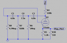
There's a phase-shift oscillator that runs at about 6.5Hz. Unusually, its only connection to the outside world appears to be on the cathode, which goes off to the 4-pin umbilical to the control panel. It has two cathode resistors that take different physical paths to ground ... can't figure that one out. Seems unnecessary at best, counterproductive at worst.

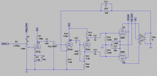
The amp proper (coming in from the RCA that I've labeled "input 1") is standard stuff: preset variable attenuator, into a voltage amp, through the expression pedal, into another voltage amp, AC coupled to a bootstrapped concertina, into a cathode-biased push-pull EL84 pair. No grid or screen stoppers. Some amount of GNFB.
I'm not sure exactly how the diode at the input comes into play. I assume that that pin on the connector is returning the signal from the control panel, and it's there for protection, but since I don't know exactly how the signal is routed around, I can't say.

As for condition ... things are generally in good shape. Most of the caps are either ceramic or poly, and appear to be in spec. A couple of the (presumed paper) caps are off. Some of the resistors have drifted a bit, some are WAY off (one of the 220k plate resistors is measuring 3M!).
Game plan is to replace the electrolytics, any out-of-spec signal caps and resistors, find the break in the heater circuit, then bring it up slowly and test each "module" on its own to make sure it's doing what I think it's supposed to be doing. May throw in some grid and screen stoppers on the power tubes, just for stability and safety's sake. All in all, not a massive job (he said, knowing full well he was dooming himself to hours and hours of frustrating troubleshooting by doing so). I'm getting my bench back in shape this weekend, and I'll have a couple days off next week that I can throw a little time at it and see what happens!
The power supply is ultra-traditional: cap input, with B+, screen, and preamp supplies. The heaters are elevated from the cathodes of the EL84 pair:

The RCA input that I've labeled as "Input_2" is a 12AX7 voltage amp and bootstrapped cathode follower. The input has an attenuating second-order high-pass filter that simulates at -3dB at 288Hz and -6dB at 177Hz. I can only assume the huge 4.7M grid leak is to augment the cathode bias. Overall gain is about 24. I believe that this is the preamp for the mic that's sitting in the reed box.

There's a phase-shift oscillator that runs at about 6.5Hz. Unusually, its only connection to the outside world appears to be on the cathode, which goes off to the 4-pin umbilical to the control panel. It has two cathode resistors that take different physical paths to ground ... can't figure that one out. Seems unnecessary at best, counterproductive at worst.

The amp proper (coming in from the RCA that I've labeled "input 1") is standard stuff: preset variable attenuator, into a voltage amp, through the expression pedal, into another voltage amp, AC coupled to a bootstrapped concertina, into a cathode-biased push-pull EL84 pair. No grid or screen stoppers. Some amount of GNFB.
I'm not sure exactly how the diode at the input comes into play. I assume that that pin on the connector is returning the signal from the control panel, and it's there for protection, but since I don't know exactly how the signal is routed around, I can't say.

As for condition ... things are generally in good shape. Most of the caps are either ceramic or poly, and appear to be in spec. A couple of the (presumed paper) caps are off. Some of the resistors have drifted a bit, some are WAY off (one of the 220k plate resistors is measuring 3M!).
Game plan is to replace the electrolytics, any out-of-spec signal caps and resistors, find the break in the heater circuit, then bring it up slowly and test each "module" on its own to make sure it's doing what I think it's supposed to be doing. May throw in some grid and screen stoppers on the power tubes, just for stability and safety's sake. All in all, not a massive job (he said, knowing full well he was dooming himself to hours and hours of frustrating troubleshooting by doing so). I'm getting my bench back in shape this weekend, and I'll have a couple days off next week that I can throw a little time at it and see what happens!
Weekend project done.
The filters (flute, trumpet, clarinet, etc.) are in a separate unit, external to the amp, and they'll need some work. The flute filter kills the signal, and the trumpet filter adds a ton of rumbly low-end noise.
As for the tremolo, I'm still not sure how it works. It taps the cathode of the oscillator and runs that to the filter unit. The trem effect is pretty weak, but that's not a problem with the oscillator, which is cycling about 150Vpp on the plate. The LFO being sent to the filter unit from the cathode is only about 400mVpp. I won't understand how it's actually using that LFO signal until I open up the filter unit.
- Heater circuit failure was a cold solder joint.
- New electrolytics and dropping resistors.
- Installed 3-prong cord and 1A fuse.
- Replaced two failed paper caps in the trem oscillator. One (mylar) power tube coupling cap was intermittent, so I replaced them both.
- Replaced about a dozen out-of-spec resistors.
- Replaced power tubes with old Mesa pulls, because I can sell these still-good 1961 Siemens-made EL84s on eBay for way more than I paid for the whole organ.
- Shared 130R cathode bias resistor was actually 110R. Ended up replacing with a 120R, which left the cathode at 9V, idle current about 33mA/tube, and dissipation at a comfortable 9.5W.
- Installed a line out using a 1:10 voltage divider from the speaker output.
The filters (flute, trumpet, clarinet, etc.) are in a separate unit, external to the amp, and they'll need some work. The flute filter kills the signal, and the trumpet filter adds a ton of rumbly low-end noise.
As for the tremolo, I'm still not sure how it works. It taps the cathode of the oscillator and runs that to the filter unit. The trem effect is pretty weak, but that's not a problem with the oscillator, which is cycling about 150Vpp on the plate. The LFO being sent to the filter unit from the cathode is only about 400mVpp. I won't understand how it's actually using that LFO signal until I open up the filter unit.