Hi all,
I am working on a TPA3251 project for a while with some good components like;
Inductors, 7uH Würth 7443630700,
Main reservoir caps, United Chemicon's 2000uF/50v 25mohm x 4
After regulator electrolytic caps, all ultra low esr polymer
Signal line caps, all metallyzed polyproplene and polyester type (no ceramic caps on signal line)
Decoupling caps, Elna Silmic 2
Opamps, OPA1656
Linear reg, ultra low noise LT3045 etc...
Also, its possible to make PFFB configuration with THT components on bottom side with point to point tehcnique. (because its too hard to make it with SMD components).
NFB lines are appx 55mm for each channel which is some long.. But the circuit can work without PFFB.
Anyway,
TPA3251, LT3045 and LM5010 chips are still available on Aliexpress market.
So I think its worth to make a good amp.
What do you think about my schematic and PCB layout?
Any comment will be helpfull.
Thanks in advance.

Hi, I have a similar project but using a TPA3255
Could you please share a more detailed image of the layout?
This is my design, Maybe we could help each other.
I find this document in the process of investigating the best way to ground the TPA, I hope it could help you
Could you please share a more detailed image of the layout?
This is my design, Maybe we could help each other.
I find this document in the process of investigating the best way to ground the TPA, I hope it could help you
Attachments
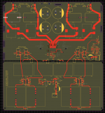
I use 3 different gnd planes;Hi, I have a similar project but using a TPA3255
Could you please share a more detailed image of the layout?
This is my design, Maybe we could help each other.
I find this document in the process of investigating the best way to ground the TPA, I hope it could help you
The left one on top layer is for analog gnd, it is connected to power gnd via a very low ESR ferrit bead,
Gnd plane under the TPA and right of it is for just TPA chip,
And for the LM5010 I use another plane directly connected to TPA's plane.
Here more detailed layout,
A note;
Don't put 0805 caps, resistors etc. around TPA chip under the heatsink. I use 0402's fot TPA.
Don't put 0805 caps, resistors etc. around TPA chip under the heatsink. I use 0402's fot TPA.
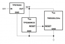
No its optional. Normally I use TPS3809 for reset. 10K/100n is instead of it.Are you sure about the 10K resistor In the reset circuit?
This is the schematic of the application note, as far I can see this is not open drain