Hi Fellow DIYers,
Recently I acquired one of this, and one of C565BEE. Upon checking with
the service manuals, I was surprised to see that the mute circuit seems to
be wrong.
In the 545, the muting transistors are 4x 2SD655F's; in the 565, they are
4x BC846B's. All these transistors seem to have the "e" and "c" pins swapped!
In the 545, these are installed, while the muting relay is not. In the 565,
these are not installed, while the muting relay is. So the 565 is ok.
What would you suggest me to do with the 545? Correct the pins? Remove
them? Remove them and install the relay?
By the way, the output impedance are 200 Ohm. Should I reduce it?
Thank you. Best regards,
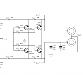
Muting transistors can be an oddity and some devices are specifically chosen and used because they possess the property of having substantial gain when reverse biased. I would leave it be.
If you reduce the output impedance then you will decrease the depth of muting. 200 ohm is fine if that is what it is.
If you reduce the output impedance then you will decrease the depth of muting. 200 ohm is fine if that is what it is.