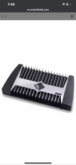
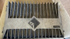
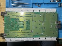
Fun rebuild I wanted to post about.l and for others. I just received this amp in as part of a larger trade/buy. Classic powerhouse from 1999! Punch 800a2, not the fabled 1000a2 but still 🙂 From those I’ve talked to so far this looks to be a common problem, so figured I’d post repair process, and in case I come across any problems while doing so.
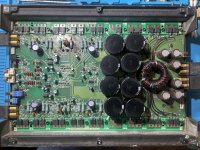
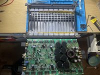
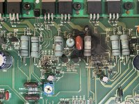
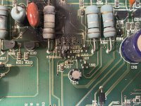
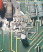
Looks like entire channel has blown, all output FETs bad, some even got so hot they lifted off the MESHA plate (another 1st for me🙂 all resistors on that side all wonky, both SMD and Throughhole types, 2 banks of BJTs look toasted, even a nice crater burned into board (but not all the way through, other side of board looks perfect actually) might need to rebuild some traces(another 1st), even the ceramic capacitor near output terminal has a hole blown through it ...needless to say a lot of firsts for me and excited to dig in on this amp.
Already have some parts on the way.
0.1Ω 5w metal oxide resistor x10 (large t-hole)
5k potentiometers and remote spade terminal
Researching BJTs currently, as with everything
I had some questions regarding the Power Supply and Output FETs. IRF640 and IRF9640, should I stick with NOS FETs of the exact type or is it advisable to go with the replacement N types (IRF640N/IRF9640N) ive been told to but I’ve also been told they cause problems on this board. Any personal experience greatly appreciated, this is more of a learning experience, 1st timers, fun project for me so time is not a factor, so I don’t mind sourcing original parts (640 seem to be hard to find atm) but any other advice/direction/better alternative then stock parts would be awesome to hear about.
I’ll post more as I make my way through amp, currently mocking up a sketch of amp, damaged parts list, stock parts and locations, probably going to recap with new better caps as well, but making notes of everything to do it proper.
Attachments
-
 6C5ACC80-1856-4E3C-A3E9-1F424C493B93.png955.6 KB · Views: 191
 -
 4160C2C6-F5CB-45F7-BDAC-35C66C509493.jpeg529.7 KB · Views: 258
 -
 32DE6117-77A5-4025-92A3-512EFFCC3BD4.jpeg776.1 KB · Views: 307
 -
 4E51D930-F7FB-4F3C-874D-D099F82517CD.jpeg600.8 KB · Views: 208
 -
 FC70D587-2F77-47BE-82E8-E59921EF7DE2.jpeg555.7 KB · Views: 195
 -
 BD2A9F8F-1DD8-4A58-A724-3A377D4D048F.jpeg576 KB · Views: 256
 -
 915302F0-B3E1-44C5-9AE2-CCB79CAE6A31.jpeg488.3 KB · Views: 214
 -
 7478C68C-CEA7-42E9-911B-7EA38F744FFB.jpeg500.7 KB · Views: 228
After cleaning the soot, the damage will be apparent and likely not significant. You may have to use a leaded resistor to go in place of the badly burned resistors after digging out the carbonized material.
NOS tends to indicate something that's unused and no longer in production. The original FETs (non-N suffix) are still available but will have a PBF suffix.
The N-suffix parts have caused problems in other Rockford amps. I wouldn't use them.
Recapping is likely pointless, as it is most of the time.
NOS tends to indicate something that's unused and no longer in production. The original FETs (non-N suffix) are still available but will have a PBF suffix.
The N-suffix parts have caused problems in other Rockford amps. I wouldn't use them.
Recapping is likely pointless, as it is most of the time.
Attachments
Wow, holy smokes Thank You for the diagram Perry! That will helps tons!
And ty for the advice/insight, and as far as capacitors I’ll just make sure they are within spec vs replacing. I was thinking maybe replacing with new “updated” caps would be beneficial but if it really won’t make that much of a difference I’ll just keep them. They really don’t go bad/aren’t as big a deal as some make them out to be huh, ty 🙂
And ty for the advice/insight, and as far as capacitors I’ll just make sure they are within spec vs replacing. I was thinking maybe replacing with new “updated” caps would be beneficial but if it really won’t make that much of a difference I’ll just keep them. They really don’t go bad/aren’t as big a deal as some make them out to be huh, ty 🙂
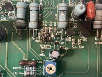
I need help identifying these parts listed so I can order replacements. I’ve tried searching for each listed in and out of parenthesis but to no avail. Any help would be much appreciated. “3S” is labeled G1 in the list
ty 🙏🏻
ty 🙏🏻
Attachments

You can get the diagrams for old amps from Rockford Tech support.
https://www.s-manuals.com/pdf/datasheet/k/s/kst5551_fairchild.pdf
https://www.s-manuals.com/pdf/datasheet/k/s/kst5551_fairchild.pdf